Shim the RED RANGER Shimmed PL Mount
The RED RANGER Shimmed PL Mount is shimmed in the factory to align to the RED RANGER it is packaged with. To shim a RED RANGER Shimmed PL Mount, use a DENZ® Flange Depth Controller (FDC), or similar tool, to measure the Flange Focal Distance (FFD).
The following shims are provided with each RED RANGER PL Mount Shim Pack:
|
Shim specifications |
||
|---|---|---|
|
Part Number |
MicronS |
Inches |
|
125-4660-001 |
13 |
.0005 |
|
125-4660-002 |
19 |
.00075 |
|
125-4660-003 |
25 |
.0010 |
|
125-4660-004 |
50 |
.0020 |
|
125-4660-005 |
75 |
.0030 |
Shim Offset Stack Table
The table below shows the offsets (as measured in microns) created by using different combinations of shims. Shimming requires no more than one (1) of each size shim and no more than three (3) total shims.
|
Offset without Shims |
Shim 1 |
Shim 2 |
Shim 3 |
Shim Total |
Offset After Shims |
|---|---|---|---|---|---|
|
50 |
50 |
— |
— |
50 |
0 |
|
55 |
50 |
— |
— |
50 |
5 |
|
60 |
50 |
13 |
— |
63 |
–3 |
|
65 |
50 |
13 |
— |
63 |
2 |
|
70 |
50 |
19 |
— |
69 |
1 |
|
75 |
75 |
— |
— |
75 |
0 |
|
80 |
75 |
— |
— |
75 |
5 |
|
85 |
75 |
13 |
— |
88 |
–3 |
|
90 |
75 |
13 |
— |
88 |
2 |
|
95 |
75 |
19 |
— |
94 |
1 |
|
100 |
75 |
25 |
— |
100 |
0 |
|
105 |
75 |
25 |
— |
100 |
5 |
|
110 |
75 |
25 |
13 |
113 |
–3 |
|
115 |
75 |
25 |
13 |
113 |
2 |
|
120 |
75 |
25 |
19 |
119 |
1 |
|
125 |
75 |
50 |
— |
125 |
0 |
|
130 |
75 |
50 |
— |
125 |
5 |
|
135 |
75 |
50 |
13 |
138 |
–3 |
|
140 |
75 |
50 |
13 |
138 |
2 |
|
145 |
75 |
50 |
19 |
144 |
1 |
|
150 |
75 |
50 |
25 |
150 |
0 |
Install Shims
REQUIRED TOOL(S): T6 TORX screwdriver, DENZ FDC (or similar tool), LOCTITE® 222
- Turn off the camera.
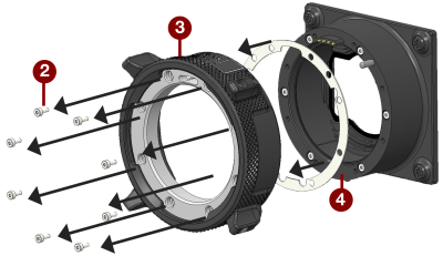
- Use a T6 TORX driver to remove the eight (8) screws on the lock ring assembly from the PL base.
- Remove the lock ring assembly.
-
Add or remove the correct amount of provided shims measured with the DENZ FDC to the lock ring assembly. Add the thinnest shims first, and then add the thicker ones, so that the thicker shims hold the thinner shims in place.

Figure: Shim Installation
- Place the lock ring assembly back onto the PL base.
- Place a small amount of LOCTITE 222 on each of the eight (8) leading threads.
- Replace and loosely tighten the eight (8) M2x6 mm screws in a cross pattern ("X" pattern) using a T6 TORX driver.
WARNING: DO NOT FULLY TIGHTEN
- Tighten the eight (8) screws evenly in a cross pattern ("X" pattern) using a T6 TORX driver to 30 in-oz, or damage may occur.
WARNING: DO NOT OVERTIGHTEN.