Input/Output Connectors
|
This section includes: |
This appendix provides pinout information for the input/output connectors on the camera.
NOTE: When connecting a cable to a connector, align the key and red marker on the cable connector with the corresponding key and marker on the device connection.
NOTE: Connector diagram images are for reference only. Diagrams are not to scale.

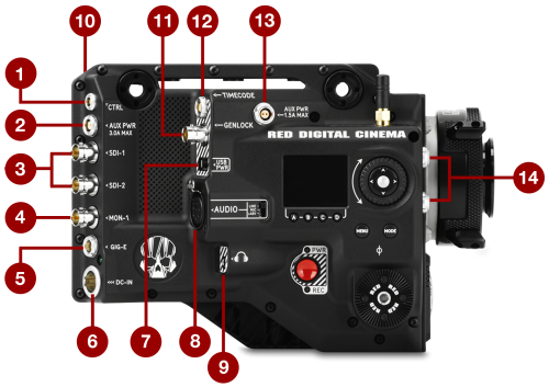
Figure: RED RANGER I/O
|
# |
Connector |
Connector Type |
Details |
|---|---|---|---|
|
1 |
CTRL |
4-pin 00B |
|
|
2 |
AUX PWR, 3.0A MAX |
2-Pin 0B |
|
|
3 |
SDI 1 and 2 |
BNC |
|
|
4 |
MON-1 |
BNC |
|
|
5 |
GIG-E |
9-pin 0B |
|
|
6 |
DC IN |
4-pin 2B |
|
|
7 |
USB |
USB 2.0 Type A (power only) |
|
|
8 |
AUDIO |
5-pin XLR |
|
|
9 |
Headphone Jack |
3.5mm stereo |
|
|
10 |
POWER TAP |
P-Tap 2-pin Female |
|
|
11 |
GENLOCK |
BNC |
|
|
12 |
TIMECODE |
5-Pin 0B |
|
|
13 |
AUX PWR, 1.5A MAX |
2-Pin 0B |
|
|
14 |
24V RS 1 and 2 |
3-pin Fischer |