Installing
Prerequisites
You must complete the following prerequisites before you can install RED Connect on a CCU.
Hardware
CCU Baseline Requirements
Your CCU must meet the following minimum requirements:
The CCU must be capable of handling the bandwidth of the incoming data stream and have GPUs/DPUs/FGPAs that are capable of decompressing and debayering the R3D data with minimal latency.
This GPU-based reference design was tested by RED and confirmed to handle 8K 60p streams for prolonged periods of time.
Motherboard
ASUS Pro ws wrx80e-sage se wifi (amd wrx80 eatx)
CPU
AMD Ryzen Threadripper Pro 3955WX 3.9GHz 16 Core
RAM
128 GB DDR4-3200 REG ECC (eight 16 GB modules)
GPU
Two NVIDIA RTX A6000 48 GB (must support NVIDIA GPUDirect). Install the latest NVIDIA driver for the A6000.
NOTE: Two A6000s are required for 8K 60p. When installing the GPUs, try to give them some physical space so that they aren’t on top of one another. Try to give them as much airflow as possible. You may not need to use two GPUs when your target frame rate and resolution are lower (8K 24p).
Networking
NVIDIA ConnectX-6 Ethernet PCI Express 4.0 card (the 10G Ethernet on the ASUS motherboard is not compatible with the 5G input).
You may need to install the NVIDIA WinOF-2 drivers from:
https://network.nvidia.com/products/adapter-software/ethernet/windows/winof-2/.
Software
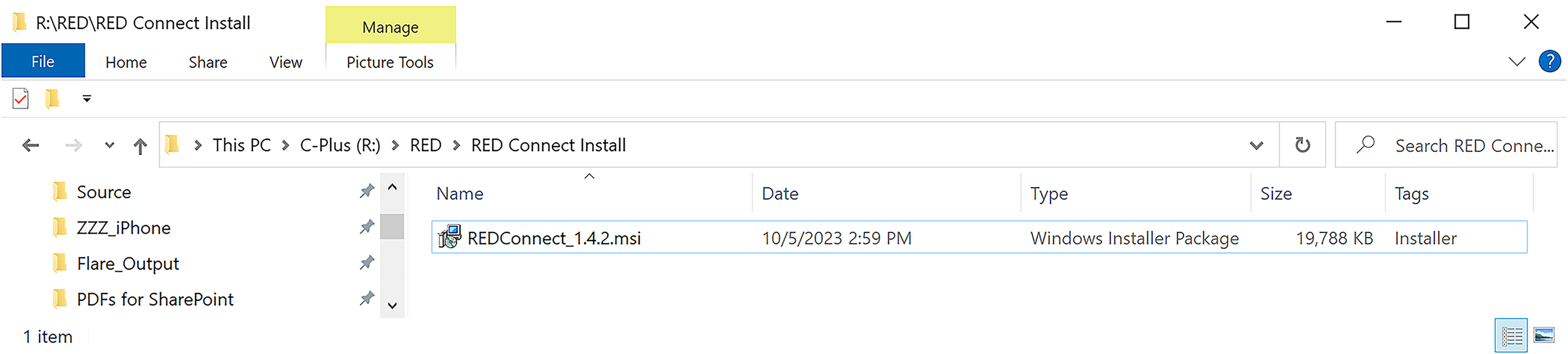
Make sure RED Connect is installed on the CCU - there may be newer versions. If upgrading, make sure to uninstall the older version before installing the newer one. The installer is called REDConnect-version number.msi.
NOTE: When you want to use SDI output from the CCU, make sure that you install the Blackmagic Design Desktop App on the CCU – download the app from https://www.red.com/download/red-connect.
RED Connect App Installation Instructions
- Download the RED Connect installation file (RED Connect-X.X.msi) to the desired folder on your CCU.
- Navigate to the folder where you downloaded the msi file, and double-click on the msi file to start the installation.
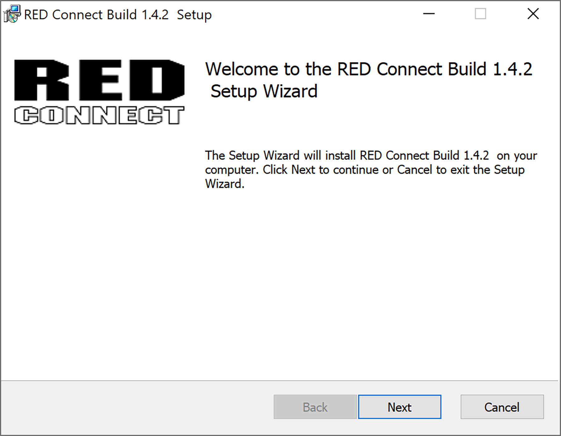
The installation wizard opens:
-
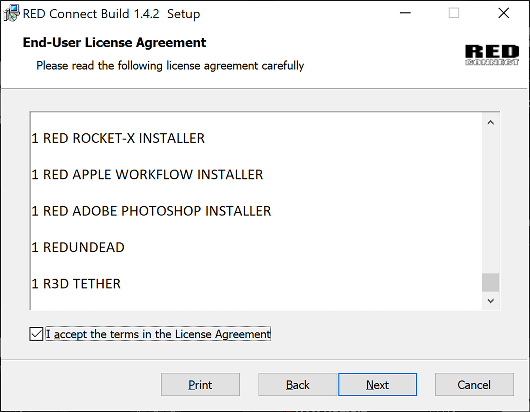
Click Next. The End-User License Agreement (EULA) screen displays:
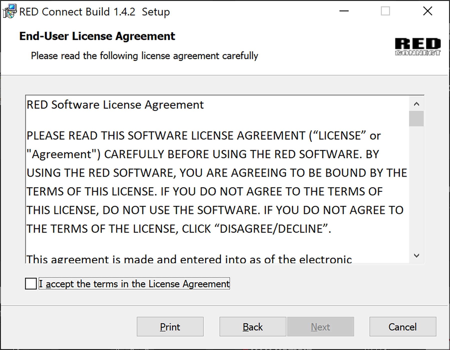
Read the EULA carefully. Accept the EULA, and click next to proceed.
The Service Account screen displays:
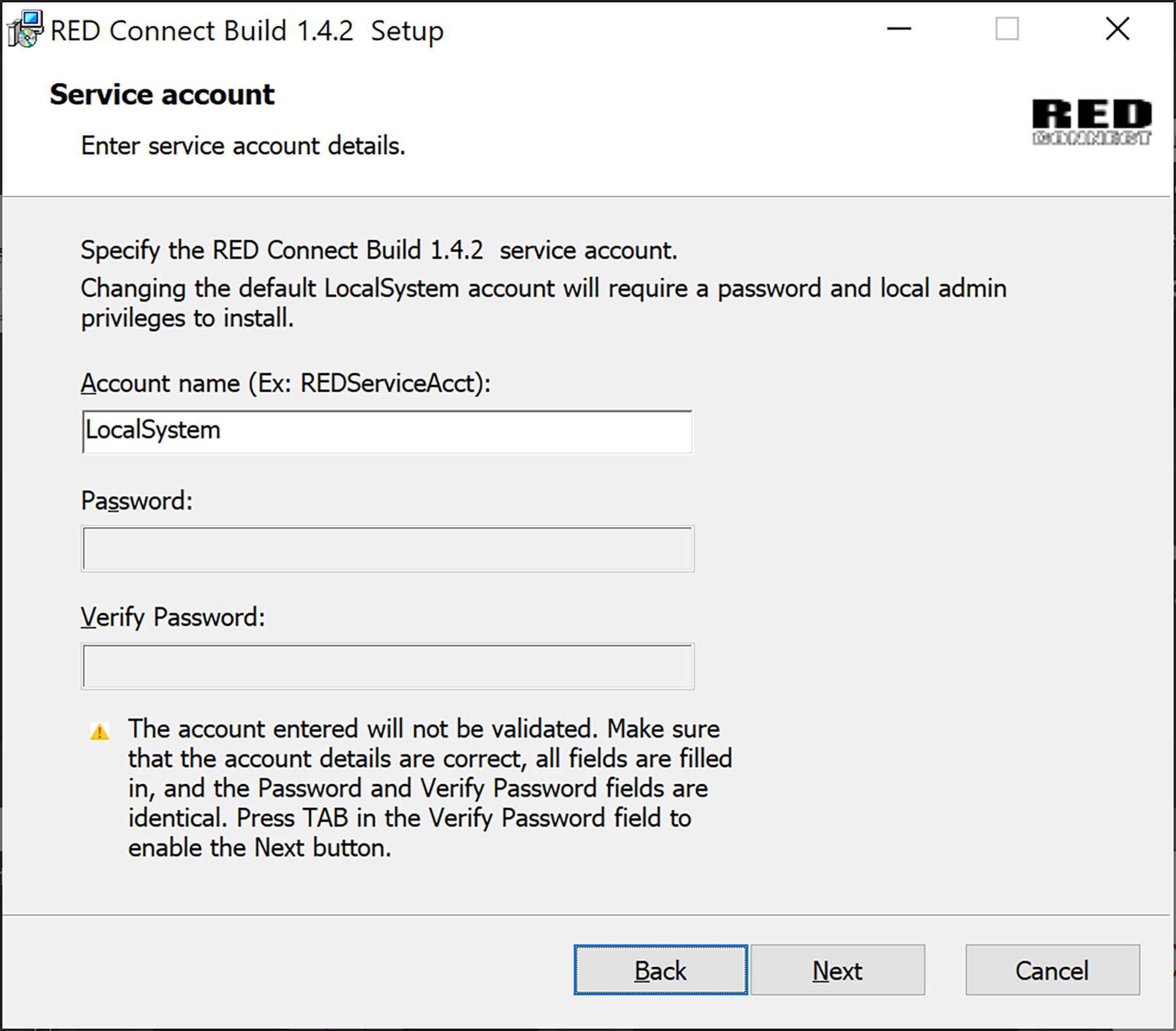
-
Click Next to continue, or enter a new account name and password and click Next. The Ready to Install screen displays:
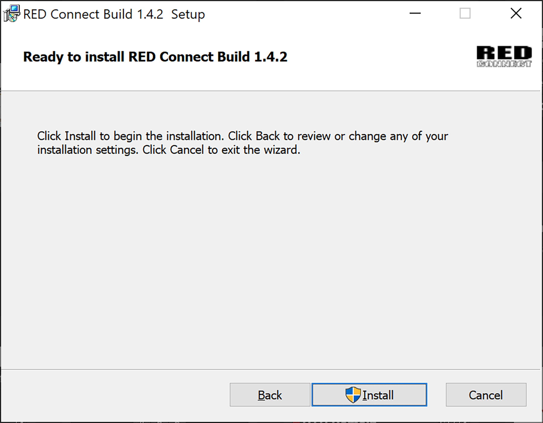
-
Click Install to begin the installation. The installation status bar displays the progress:
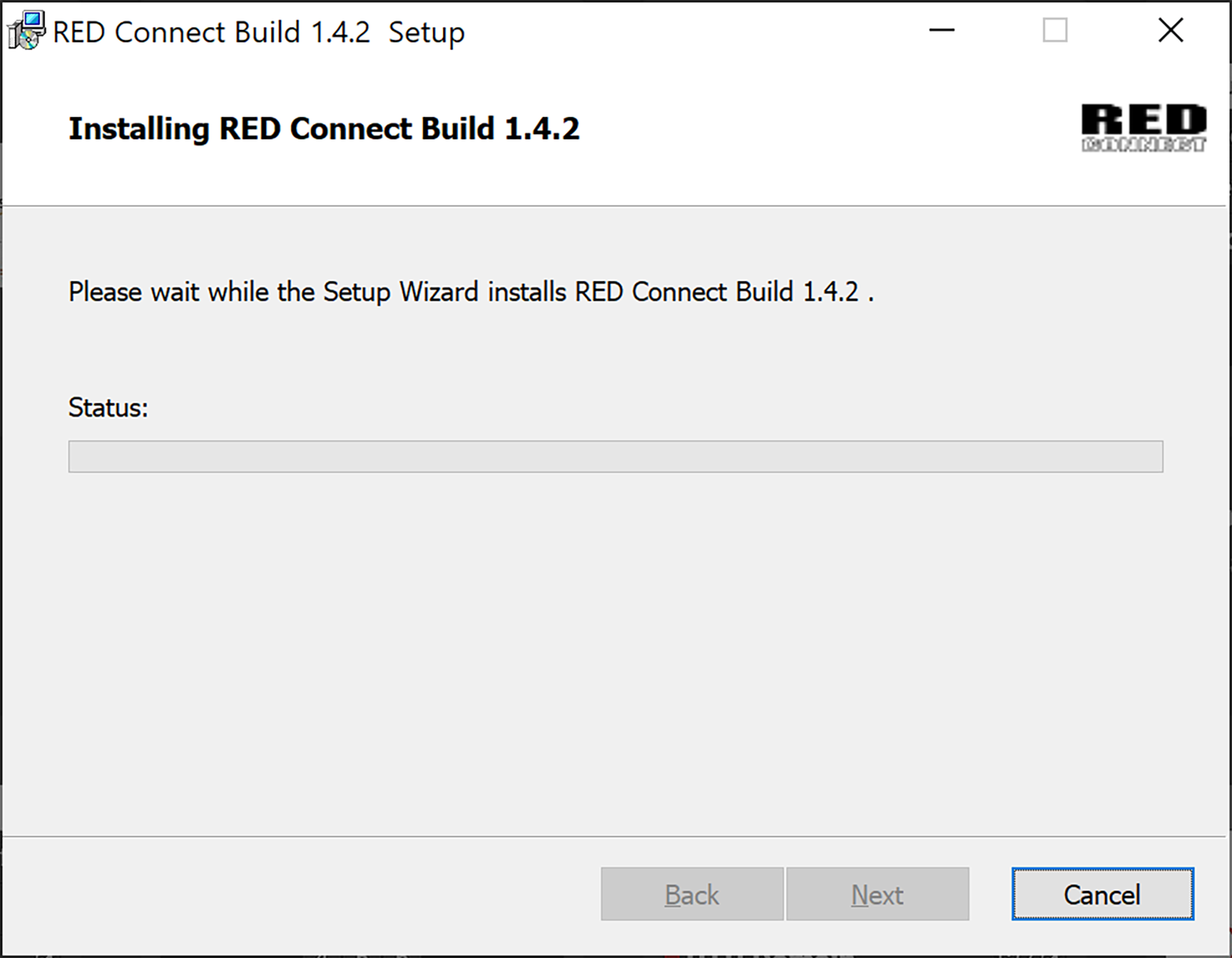
When the installation concludes, the Completed screen displays:
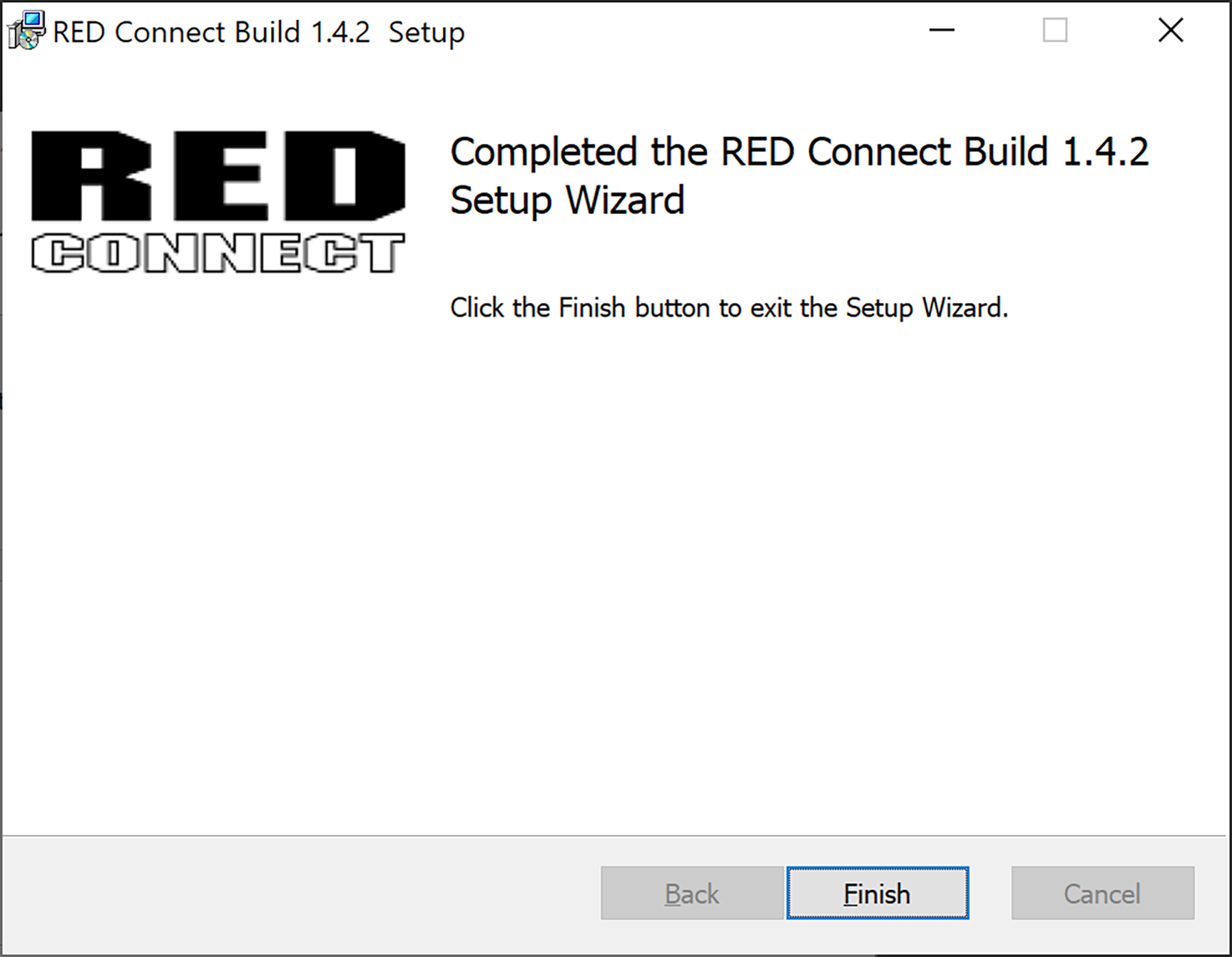
-
Click Finish.
-
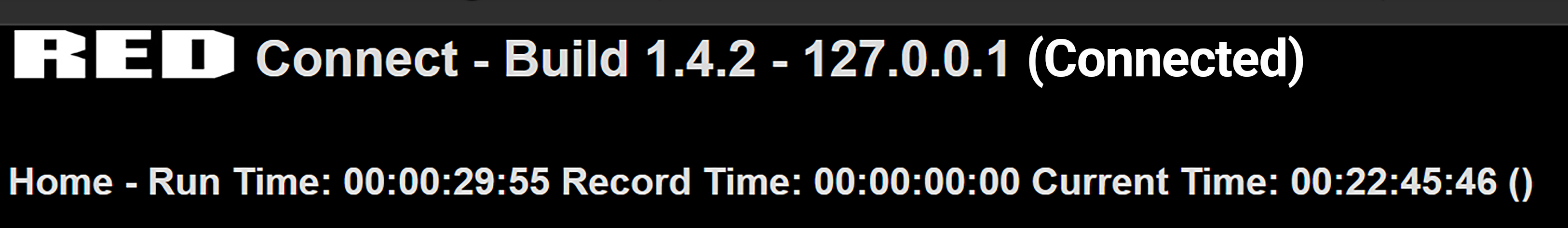
Enter 127.0.0.1:8088 in your browser to view the RED Connect home page.
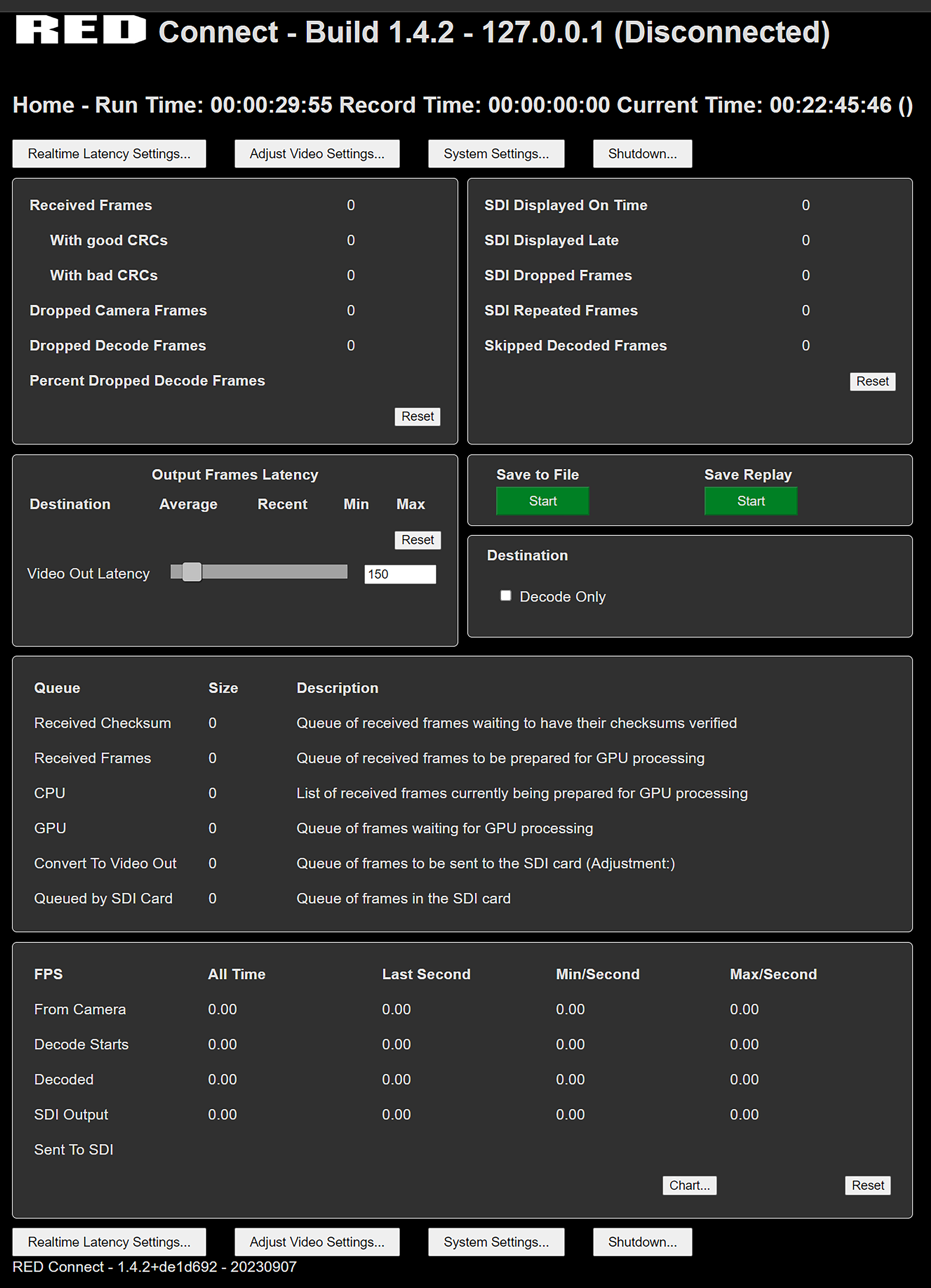
The home page displays all of the stream statistics and metrics of the stream.
If the browser does not display the home page, press Ctrl+Alt+Del to open Windows Task Manager and confirm that the RED Connect service is running.
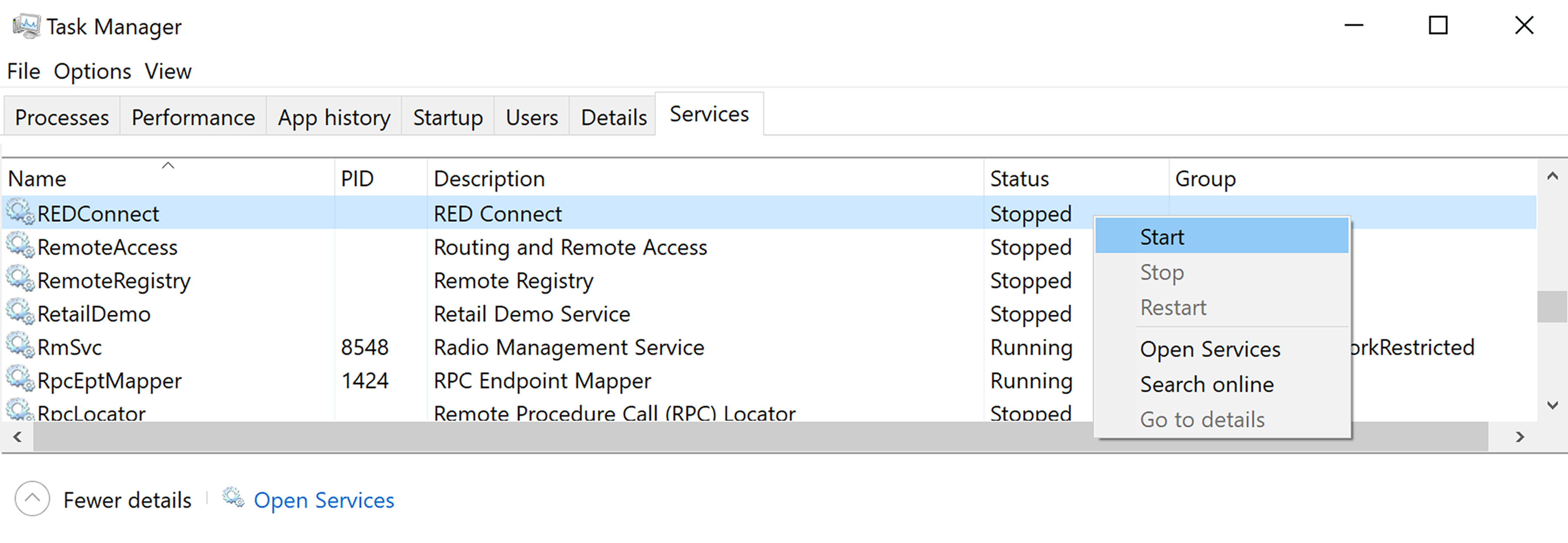
If the RED Connect service is stopped, right-click on the RED Connect service and click Start.
NOTE: A local admin account is required to install and start /stop the RED Connect service.
Connecting the Camera to RED Connect
-
Copy the RED Connect IP address from the main screen:
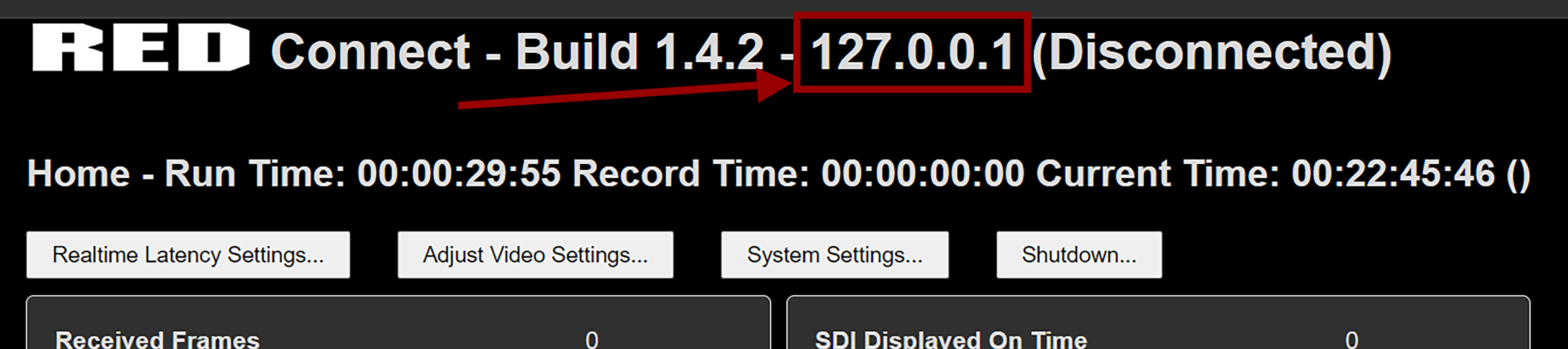
-
Install a valid RED Connect license in your camera.
-
Make sure you have valid firmware that supports RED Connect (V-Raptor and V-Raptor XL firmware version 1.5 and beyond).
-
Make a folder called "licenses" on your USB-C drive or CFexpress card.
-
Copy the *.skm file to the USB-C drive / CFexpress card "licenses" folder.
-
Insert the drive or card into the camera.
-
In Menu>System Settings>Licenses>On Media Licenses find the license file that was loaded above and click the button below IMPORT:

-
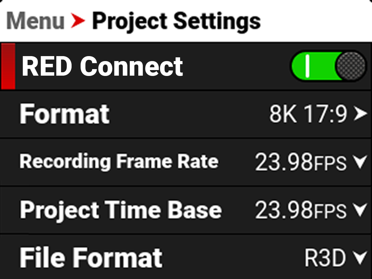
The License should activate. When you navigate the camera menu to Menu>Project Settings you should now see RED Connect with a green toggle.
-
RED Connect must be enabled to start streaming from the camera.
-
-
Make sure that RED Connect is active in camera by going to Menu>Project Settings>RED Connect. If the slider is green, the camera will have RED Connect video streaming enabled.
-
For USB-C streaming, this is disabled by default.
-
For Connected Camera Module streaming, this will be enabled as long as the module is installed, and camera power is received through the module.
NOTE: The module will not be detected properly when the camera is powered through the power port on the camera, it should be powered through the module port when using the module.
-
-
The default settings for the RED Connect app are 8K 16:9, 59.94 FPS. If you want to stream with the default app settings, change the camera settings under Menu>Project settings to 8K 16:9 and 59.94FPS.
-
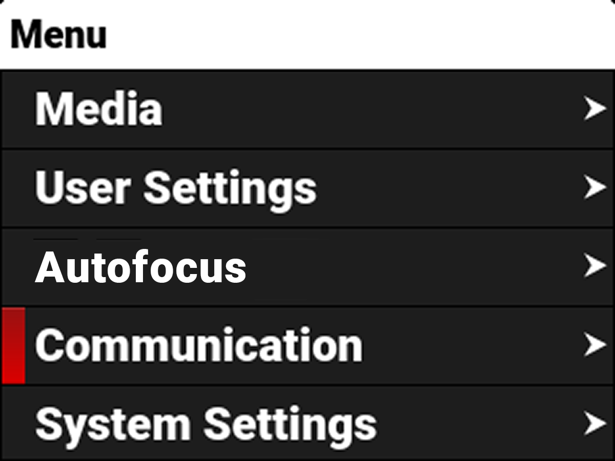
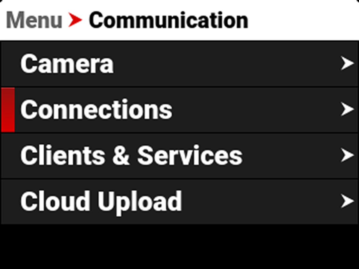
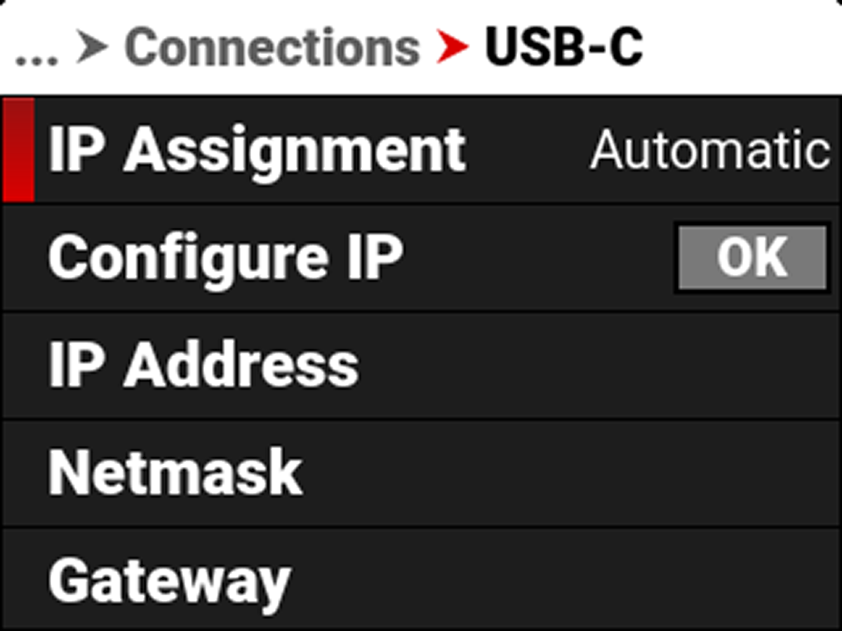
In-Camera, under Menu>Communication, select either USB-C or the Connect Camera Module, and look for the IP address of the camera.
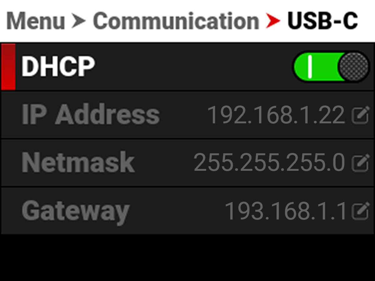
Depending on how the camera is connected to your CCU, you will either want to set this to Automatic (DHCP) or Manual IP. Refer to Networking and Camera Connectivity for more information.
-
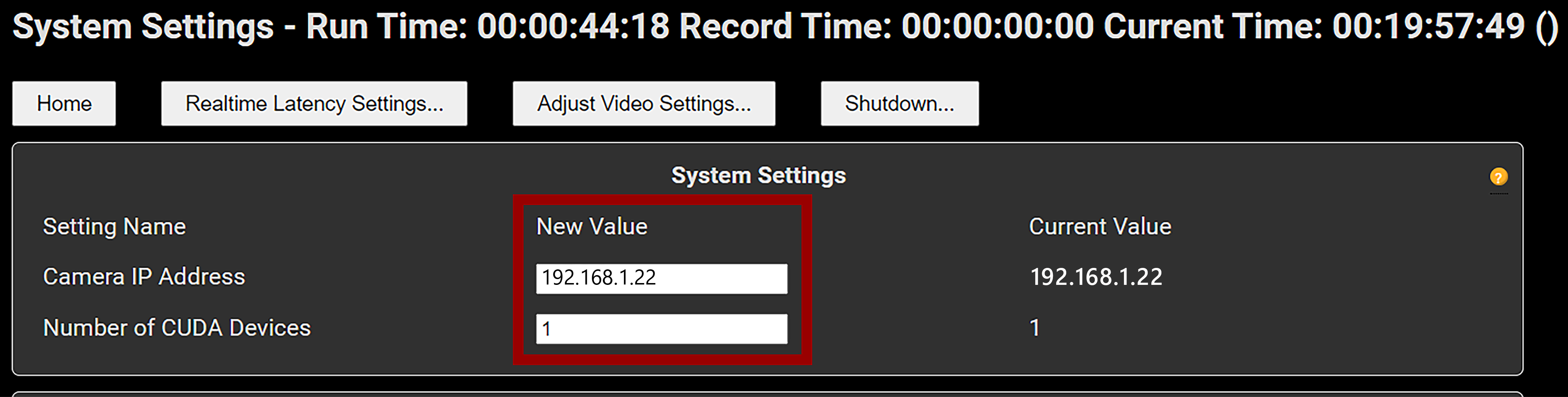
On the RED Connect App, click on the System Settings button:

-
Confirm that the IP address of the camera is correct in the RED Connect App:
-
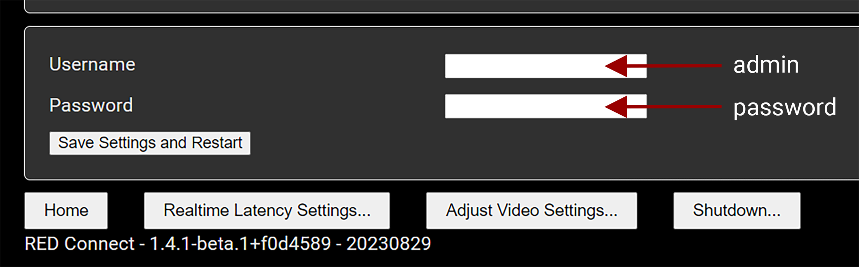
Scroll down to the bottom, and enter “admin” for username and “password” for password, and click Save System Setttings And Restart:
-
Once the camera and CCU are connected, you will see the “Connected” message at the top of the screen:
-
When you press the Record Button on the camera, the stream starts and values display on the Home page of the RED Connect App.
Networking and Camera Connectivity
Depending on the way the camera is connected to the CCU, you will want to change your IP settings in order to ensure that the camera and CCU connect.
Direct Connection (Static IP / Manual)
If you are going directly from the camera into your CCU, we recommend setting the Camera and CCU up to use Manual/Static IPs.
Camera
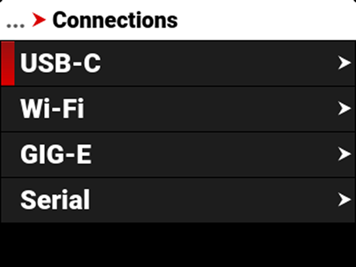
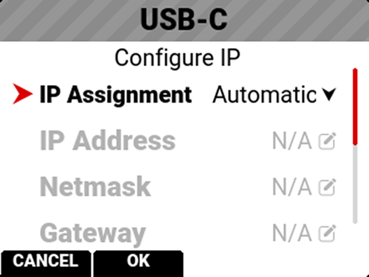
Under Menu>Communication>Connections>USB-C or RED Connect Module, click “Configure IP” and set a Manual IP address.
-
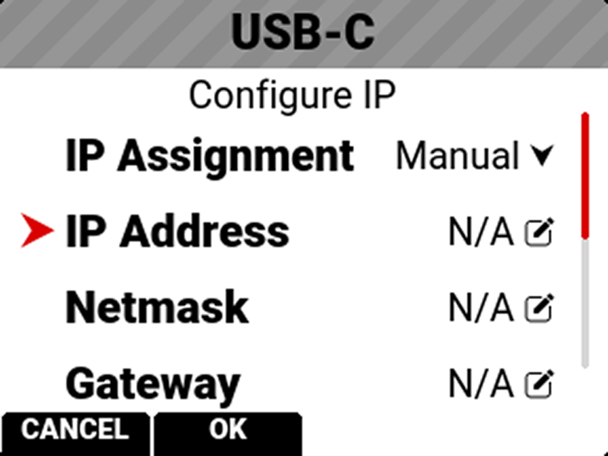
Change IP Assignment from Automatic to Manual:
-
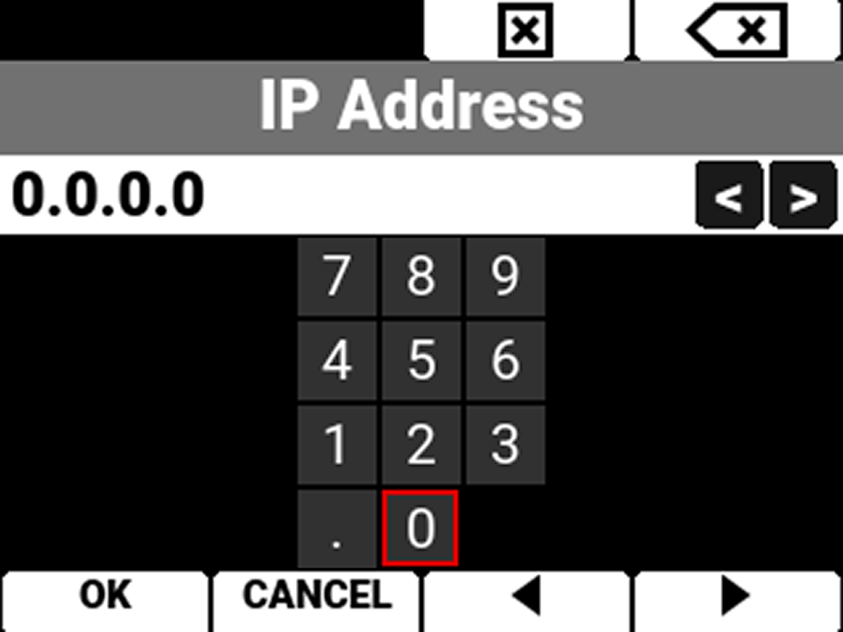
Select IP Address to enter your desired IP address, such as 192.168.10.20:
-
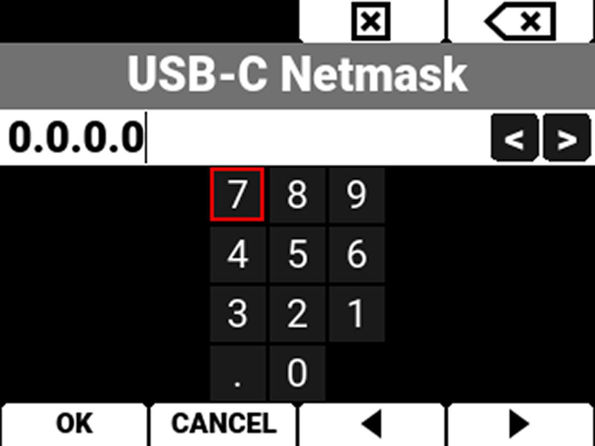
Select Netmask to enter 255.255.255.0 for the Netmask, if it has not been entered already:
CCU
-
On the CCU, open your computer’s Ethernet settings, and right click on the 10G network interface that you are using to connect to the camera:
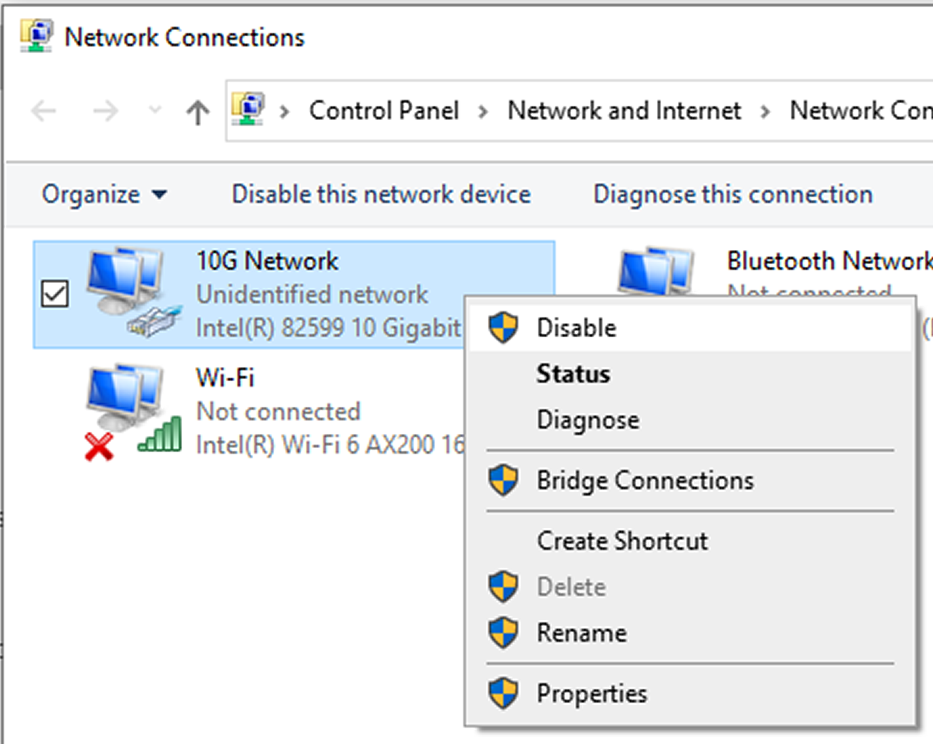
-
Click Properties, and make sure everything is unchecked besides Internet Protocol Version 4 (TCP/IPv4).
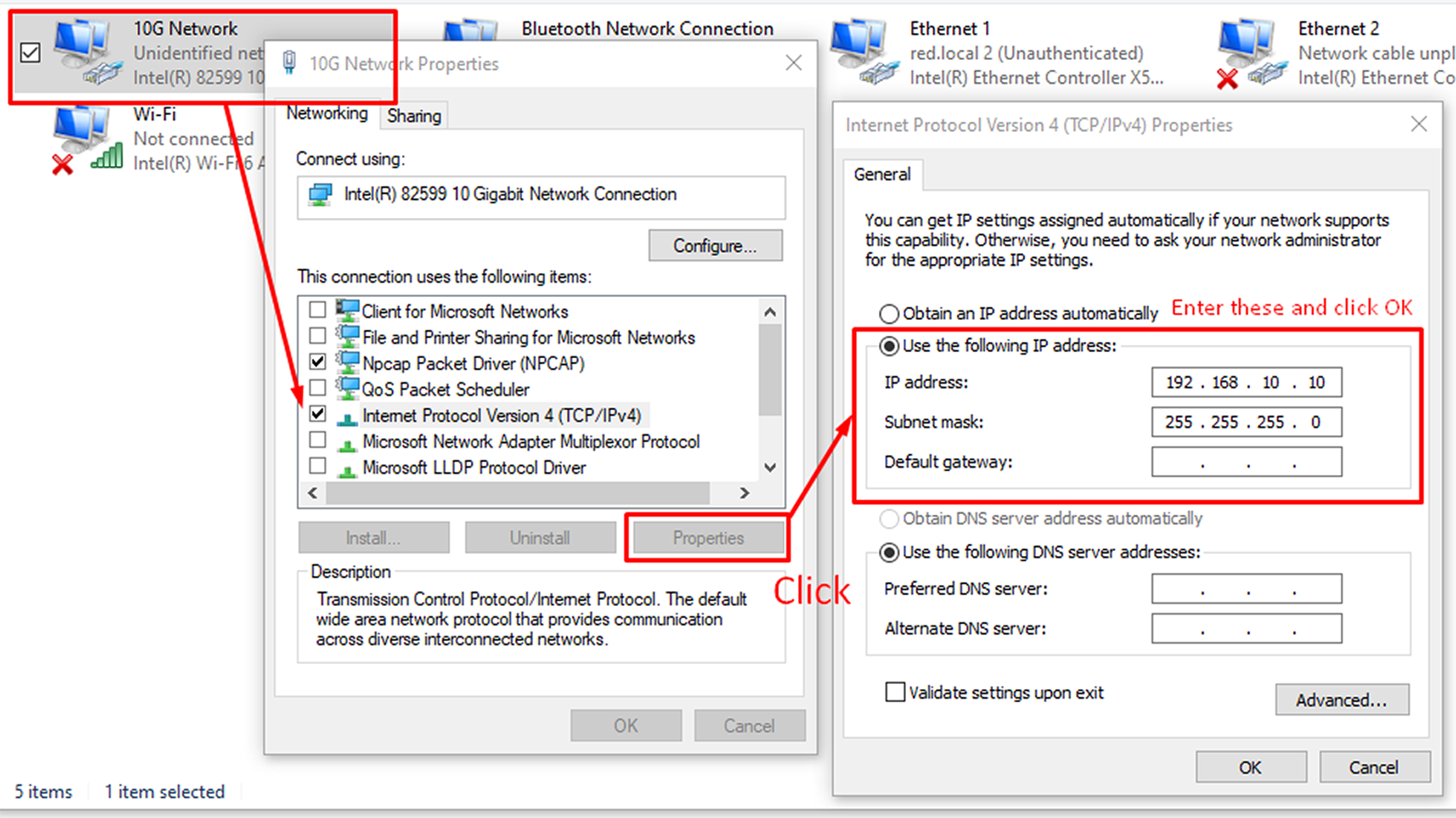
-
Click on Internet Protocol Version 4 (TCP/IPv4), click Properties, and enter the following to set the 10G interface up for Static IP:
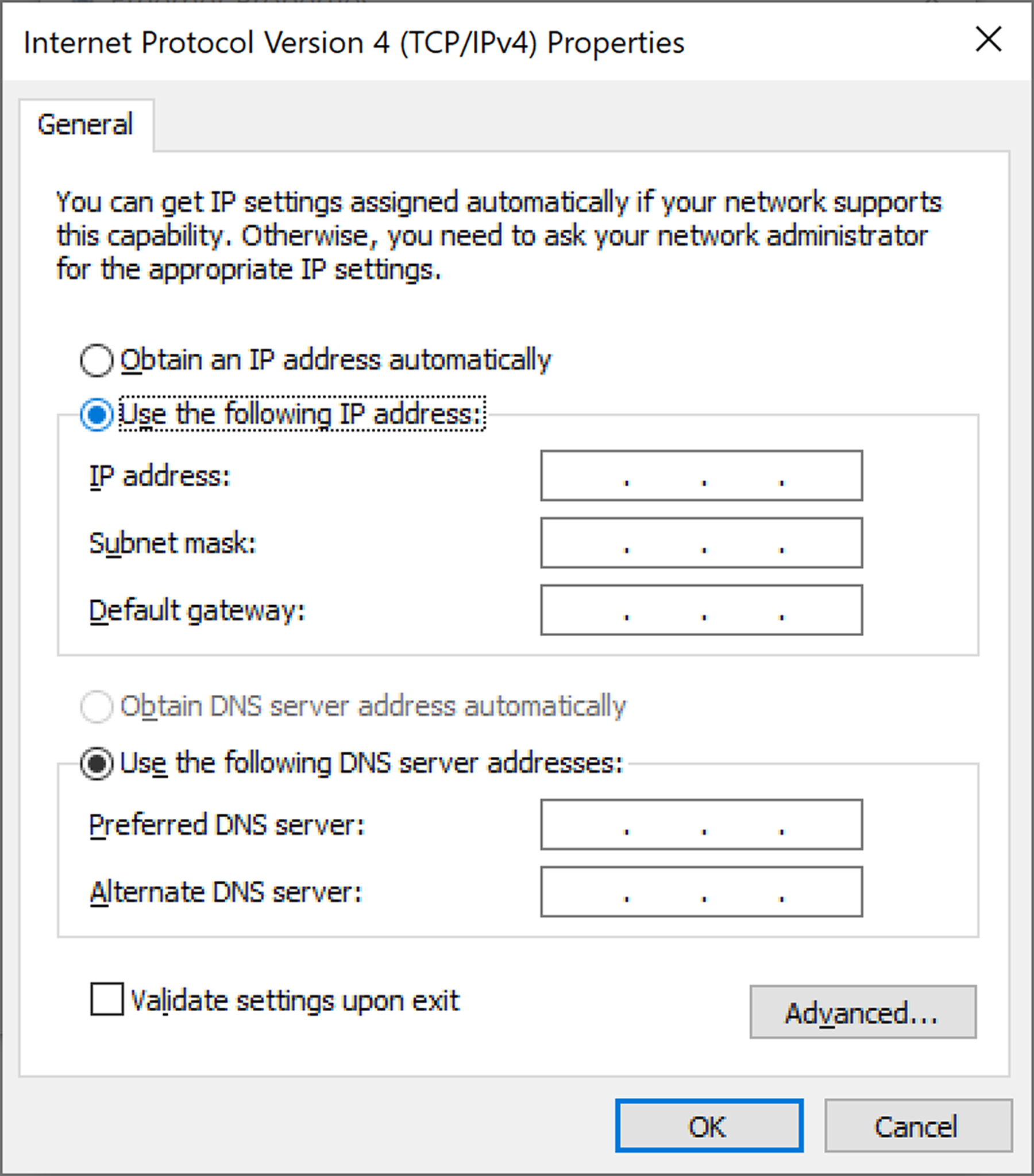
- Check “Use the following IP address”
- IP: Enter 192.168.10.10 (or whatever IP address you prefer, which is different from the IP address set in-camera in the previous step).
- Subnet Mask: 255.255.255.0
- Default Gateway: Blank
- Click OK.
Automatic IP Assignment (DHCP)
When there is a DHCP server on your network, we recommend leaving the cameras with IP Assignment set to Automatic (the default).
MTU
For most network cards, you will want to set the MTU on the 10G interface on your CCU, as well as on your camera, to 9000. Only a few cards, such as the NVIDIA Mellanox ConnectX-5 and ConnectX-6 reliably support video streaming at high bitrates with the default MTU of 1500.
Camera
-
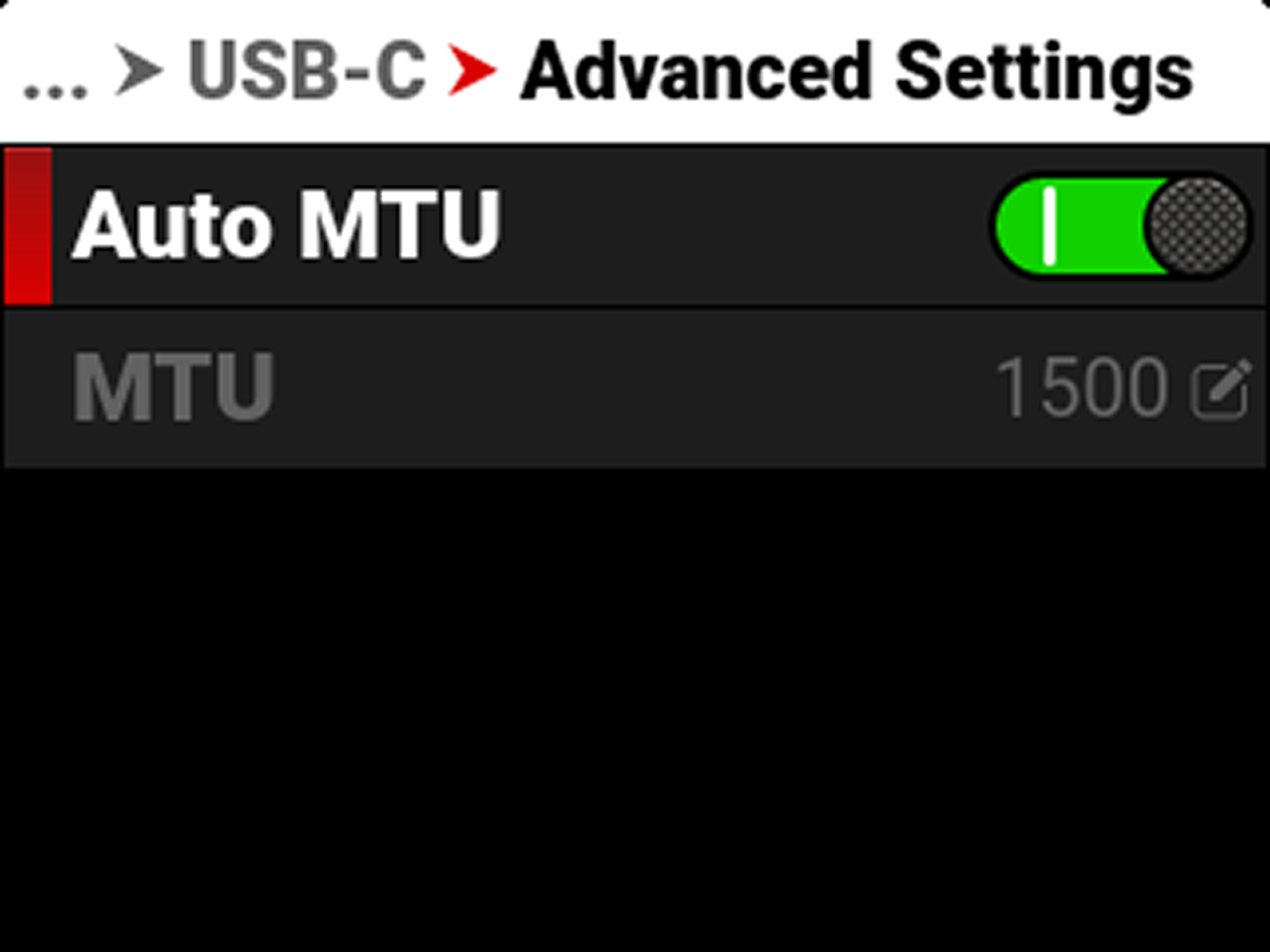
Go to Menu>Communication>USB-C>Advanced Settings and disable Auto MTU:
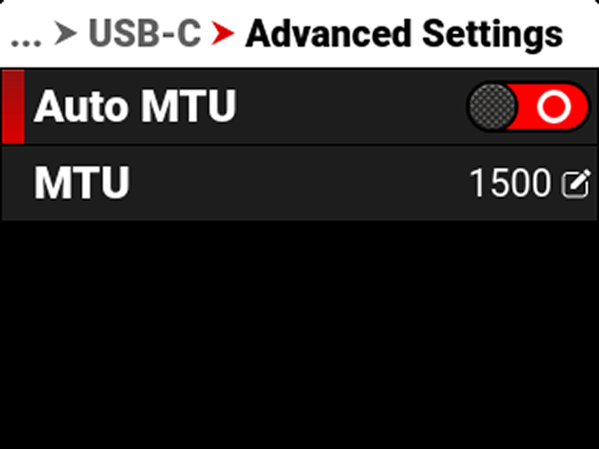
-
Change the MTU to 9000:
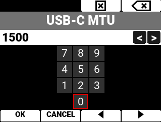
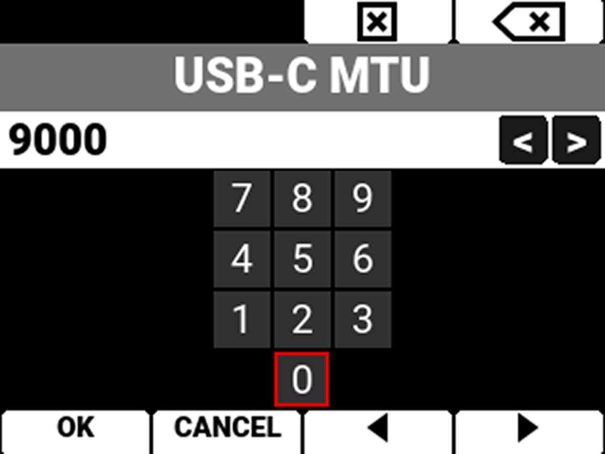
-
Press the button under OK to save the change.
CCU
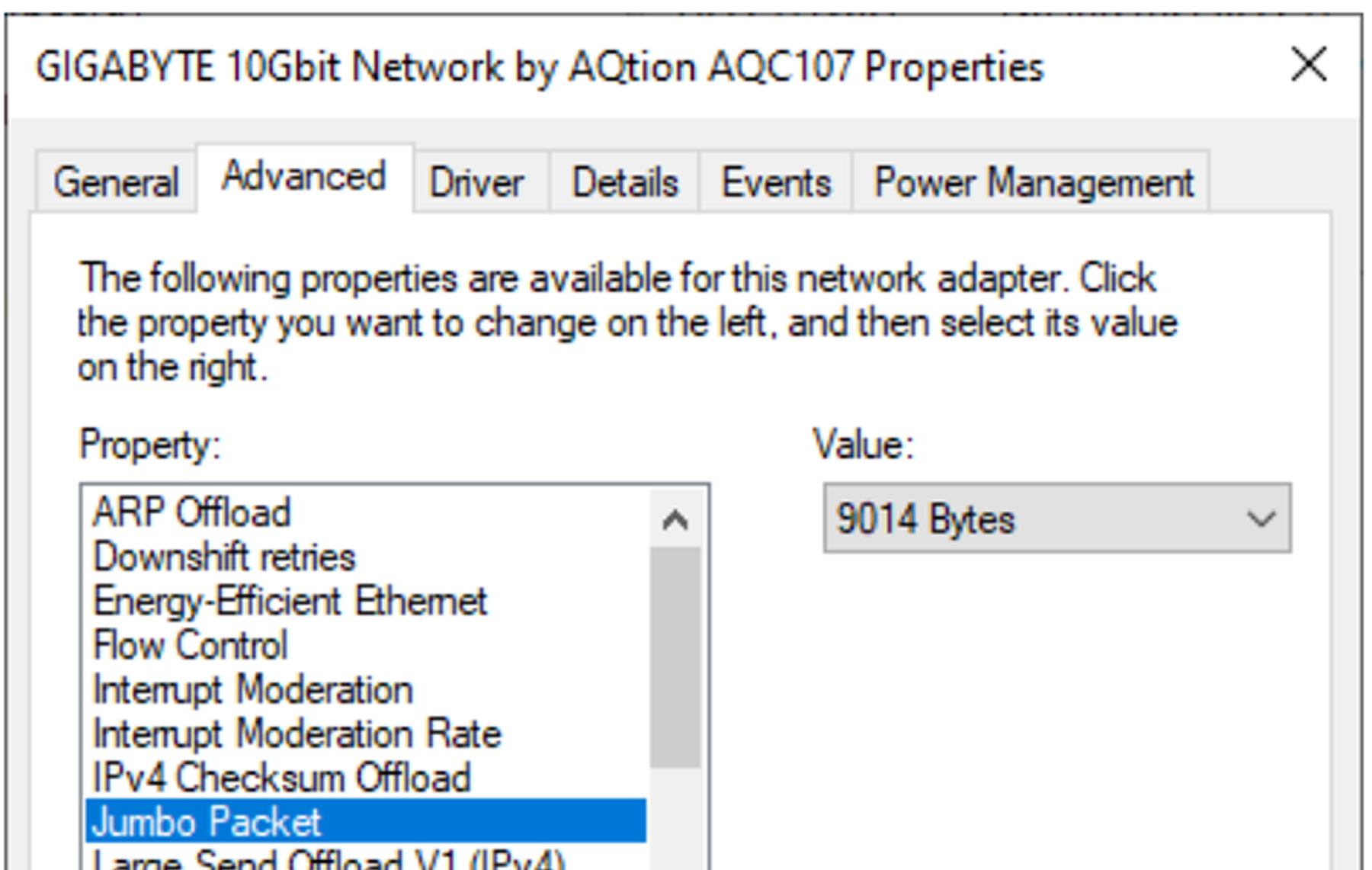
Go into the Ethernet Adapter’s Advanced Settings, and set Jumbo Packet to 9014 Bytes.
PTP
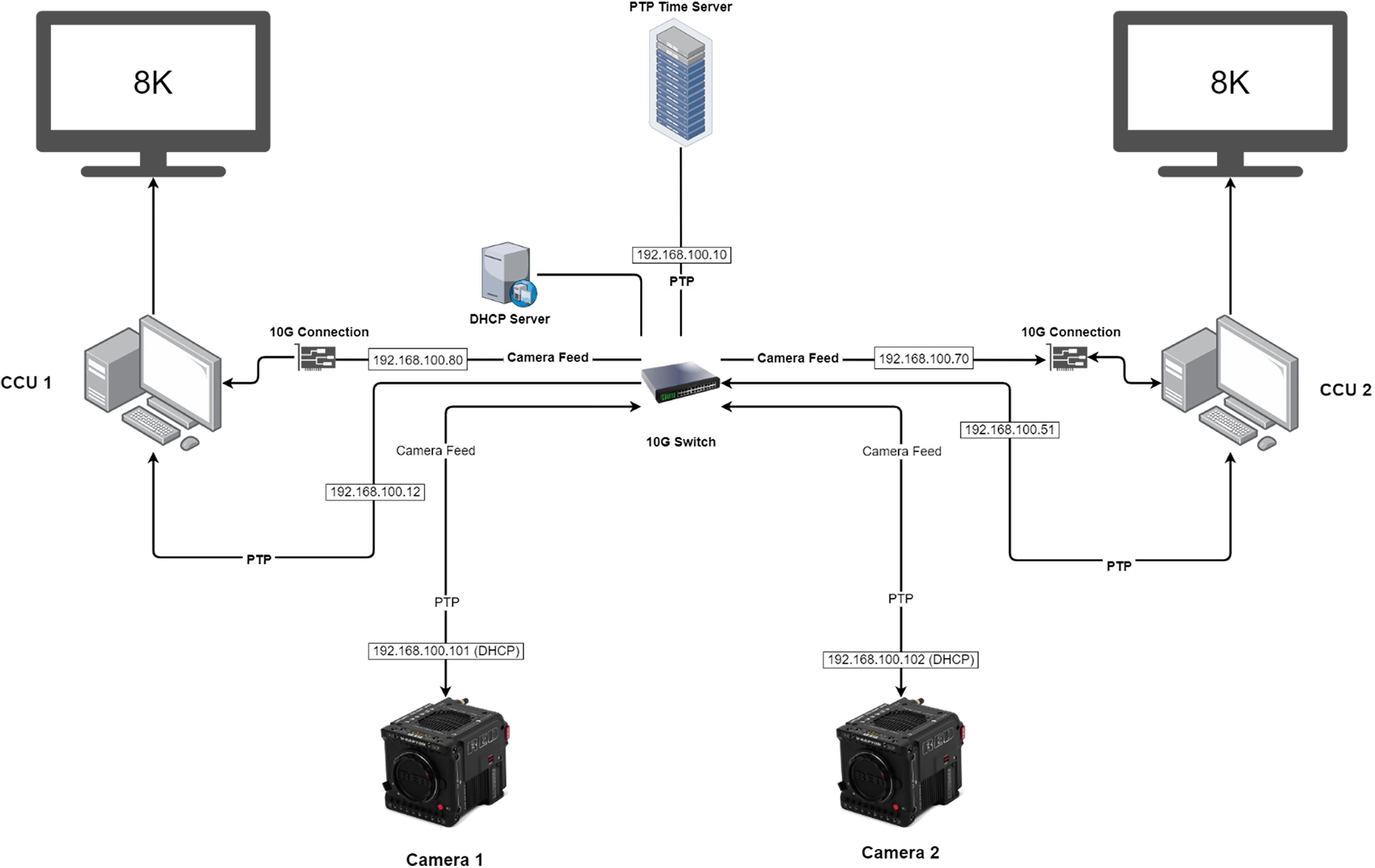
When you want to add PTP to your network, we recommend connecting your PTP source to a PTP compatible switch. Connect the PTP compatible switch to the camera and the CCU.
NOTE: You must enable PTP on both the CCU and the camera to eliminate drift between the internal clocks of the two systems. You must load a SMPTE 2059-02 PTP profile on your timeserver to make it compatible with the RED Connect system.
Below is a diagram of a sample system that RED uses extensively:
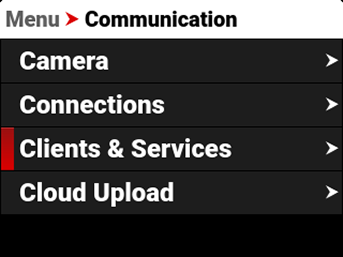
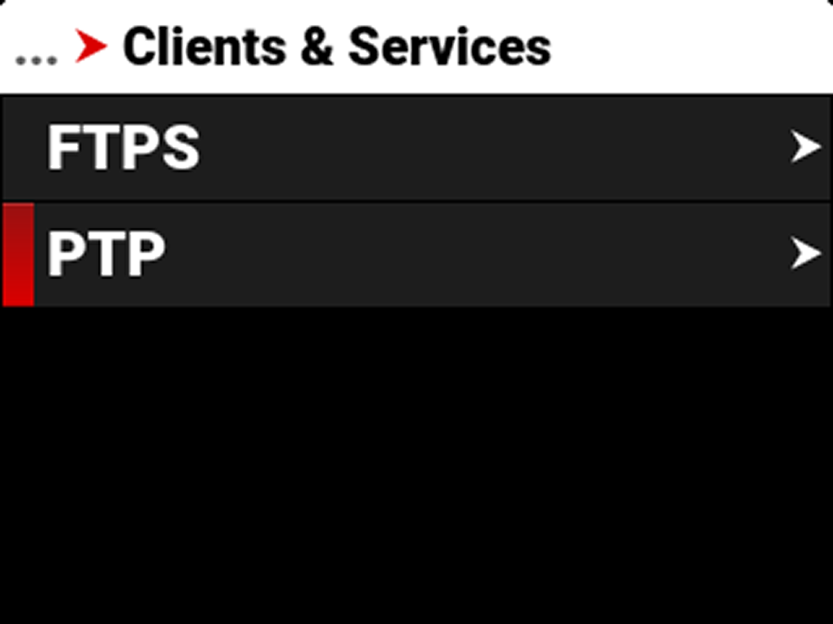
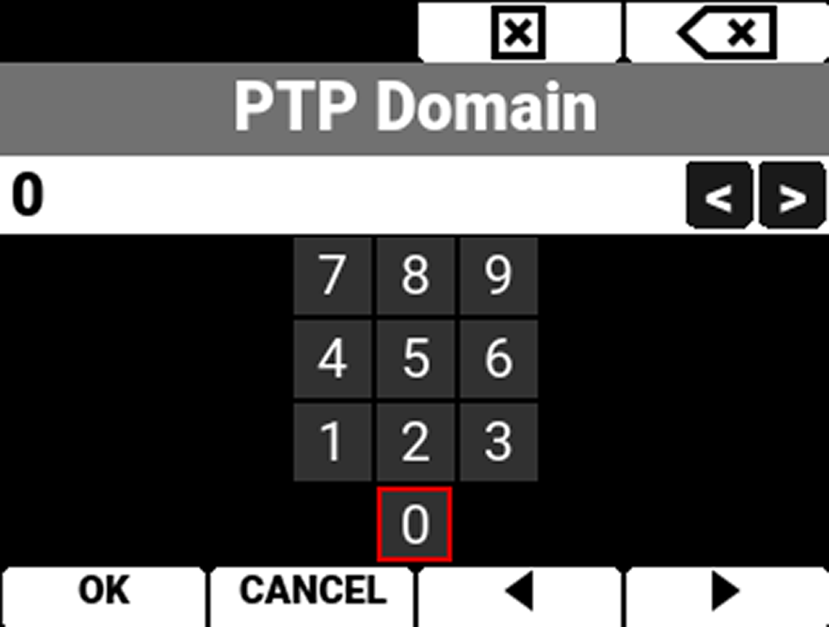
PTP can be enabled by going to Menu>Communication>Clients & Services>PTP and changing the PTP domain to the domain of your PTP server.
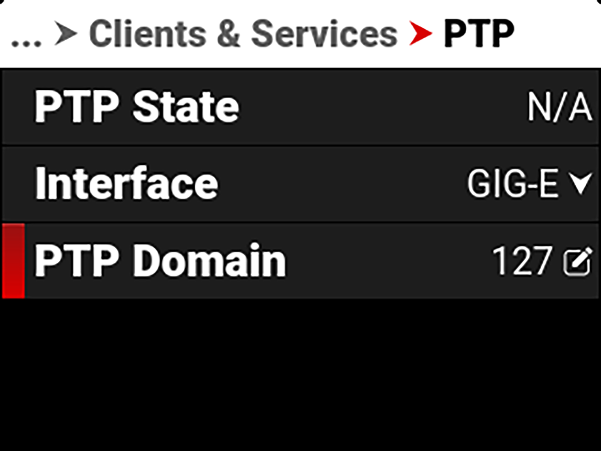
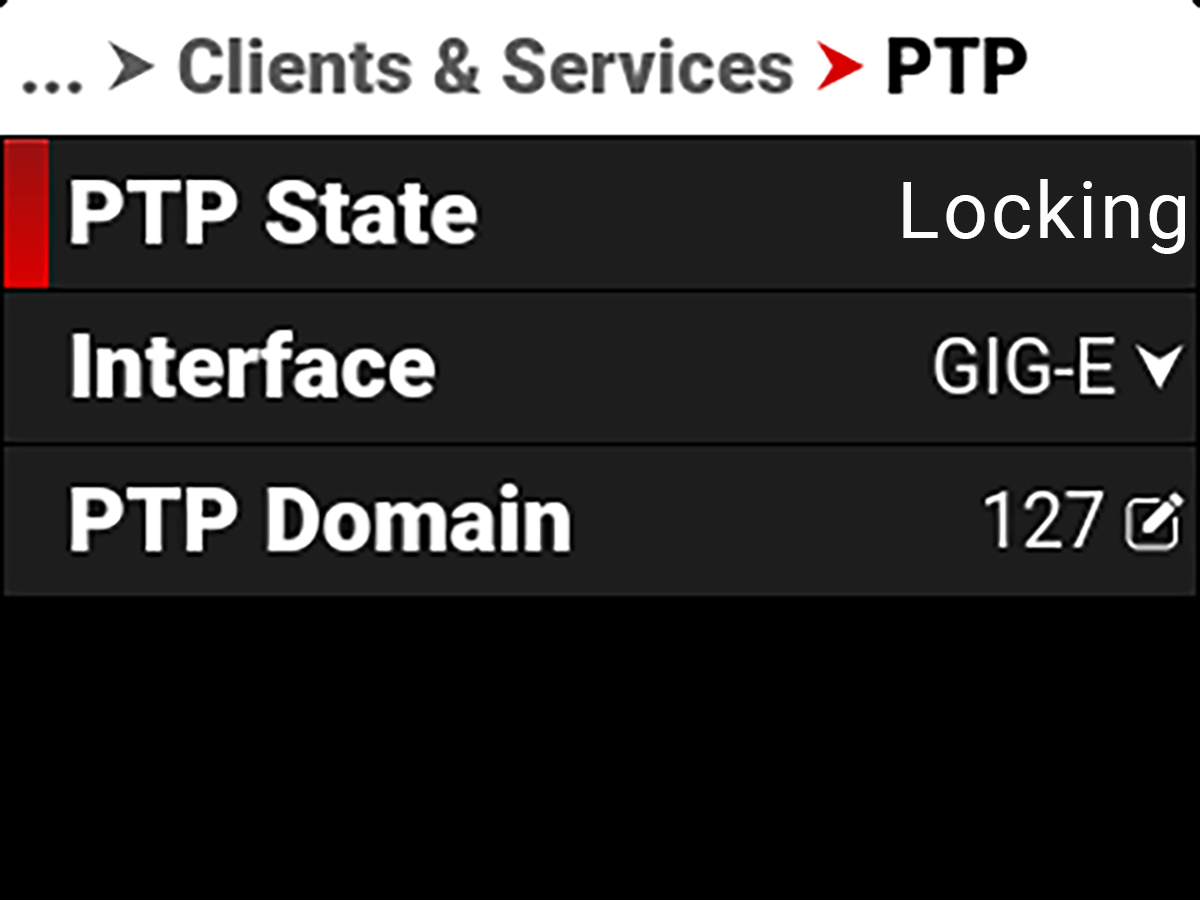
After that is enabled, you should see PTP State change from N/A to Locking, and eventually to Locked.
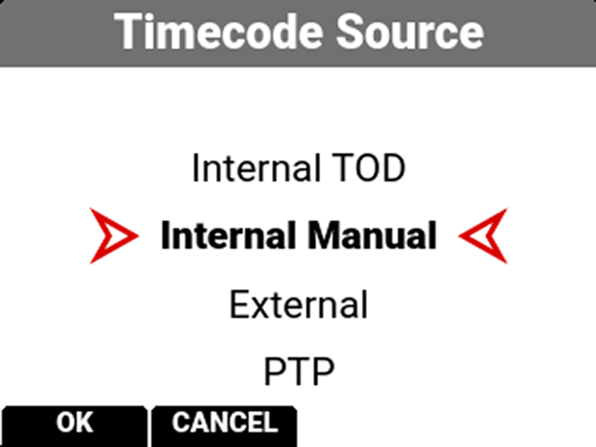
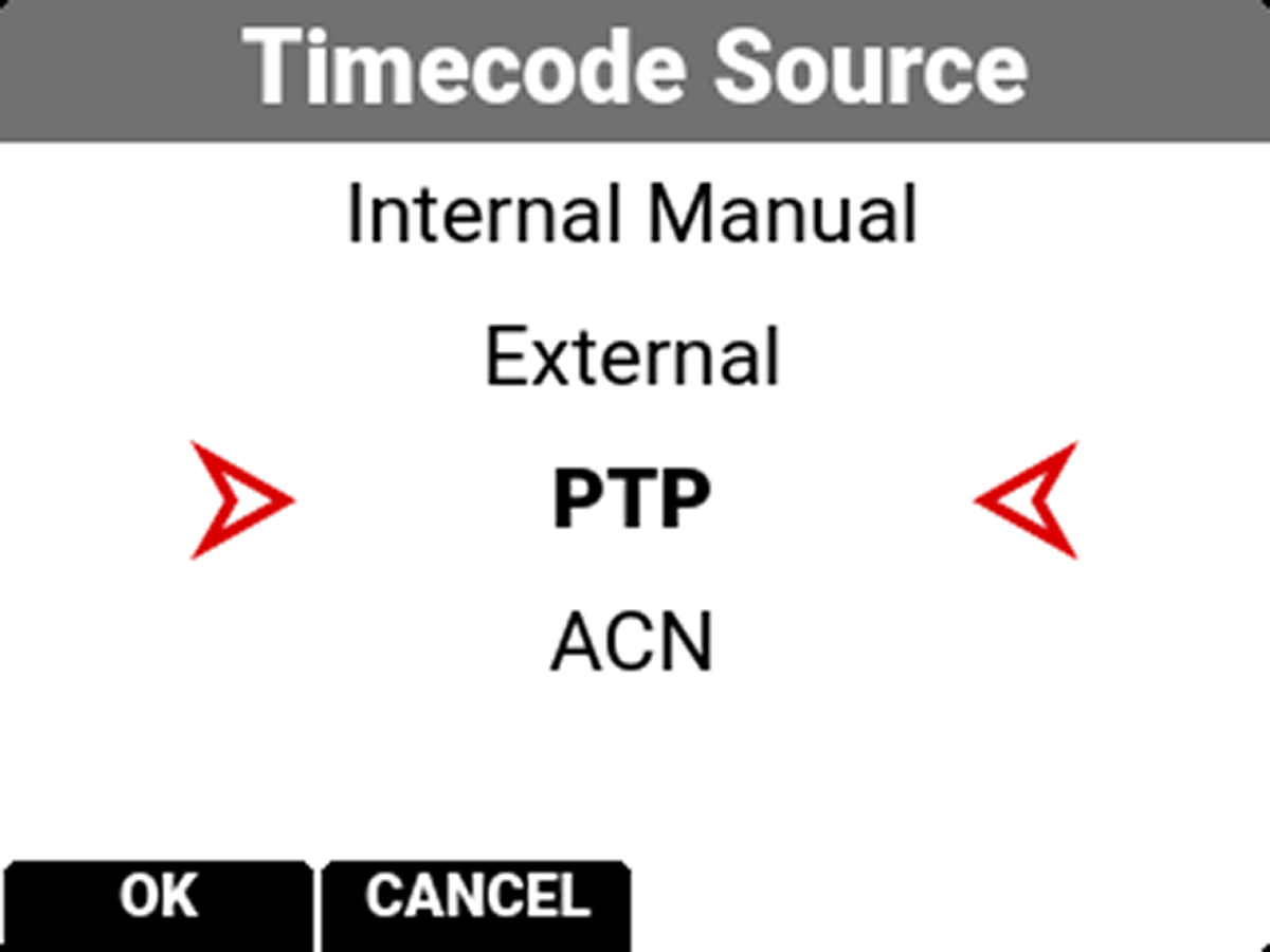
Once the PTP is locked, you can go to Menu>Audio / TC>Timecode Source and change it to PTP.
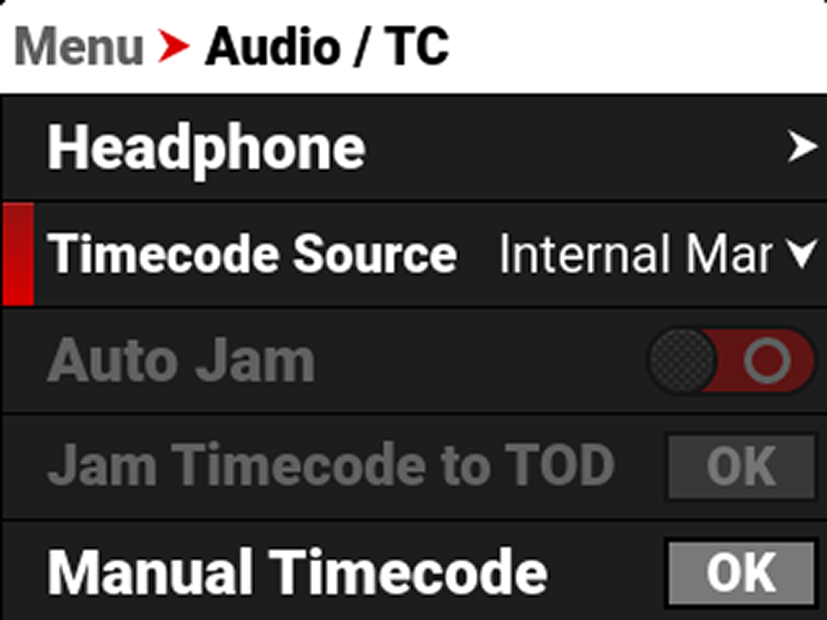
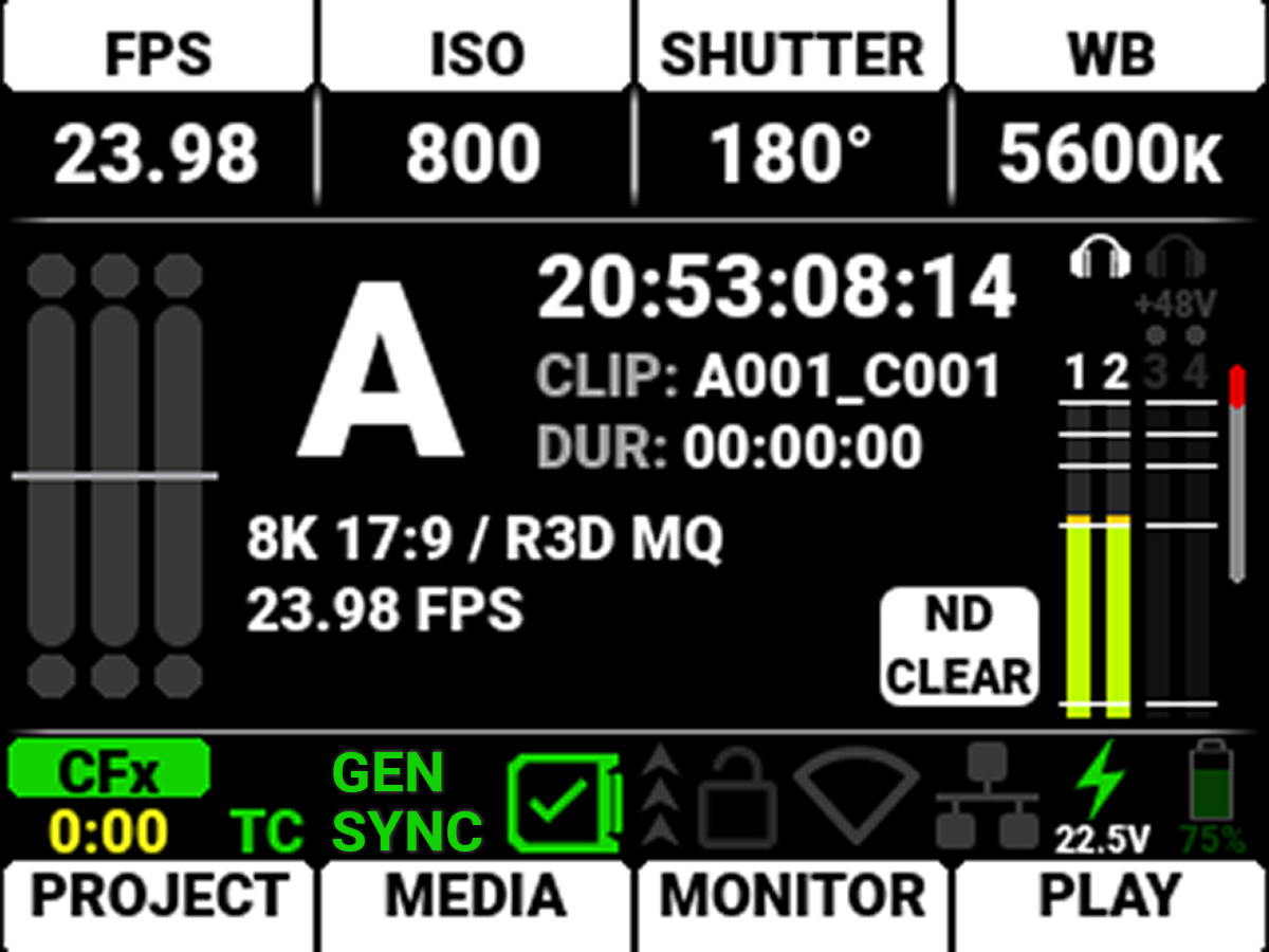
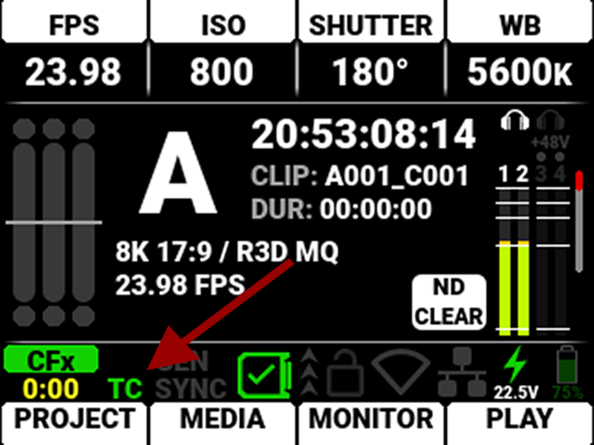
The TC indicator on the main menu of the camera goes from blank to Green. Green indicates that it is locked to PTP.
Genlock and Sync (GEN/SYNC indicators on the camera menu) can also be locked onto PTP, although that feature is only available when using the RED Connect Camera Module. This setting will not be available when PTP is locked through USB-C.
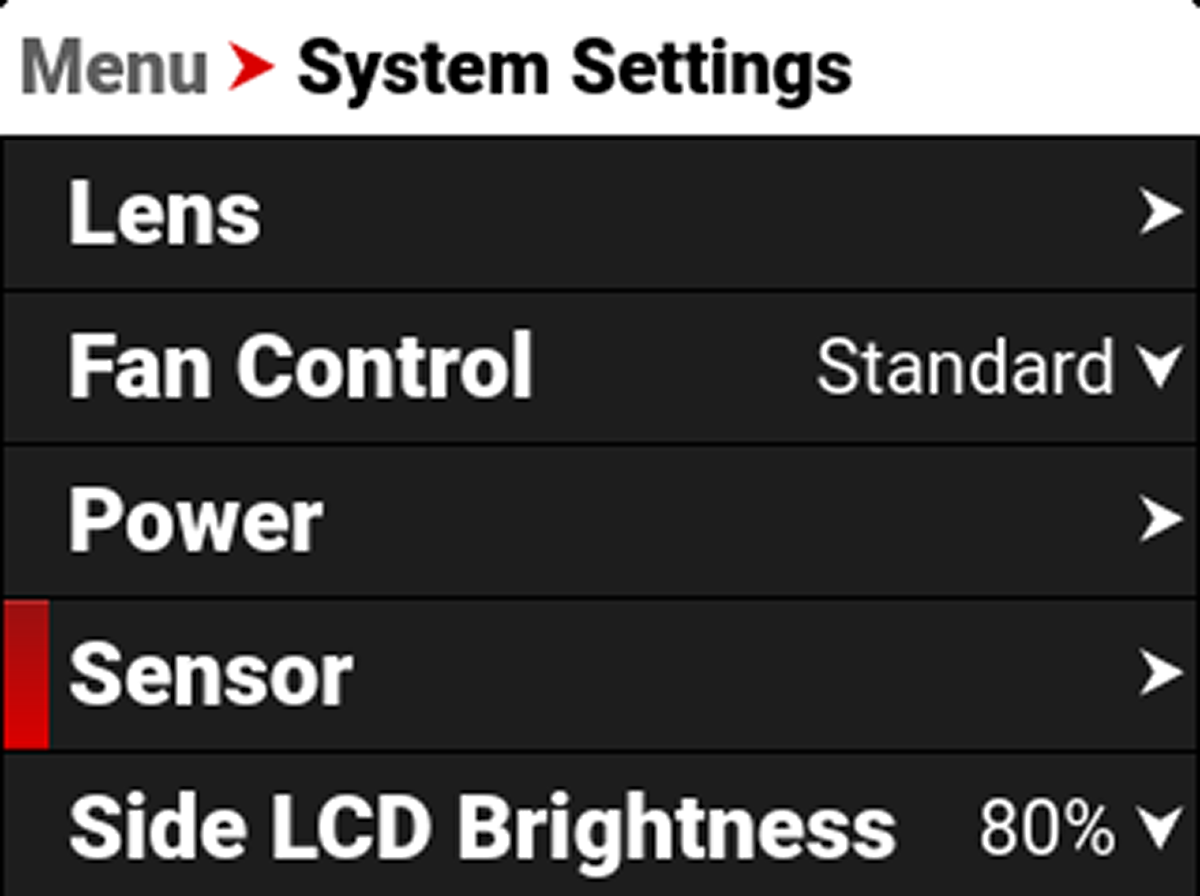
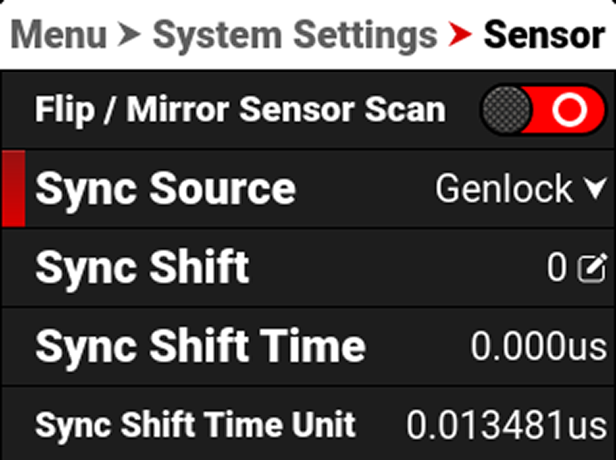
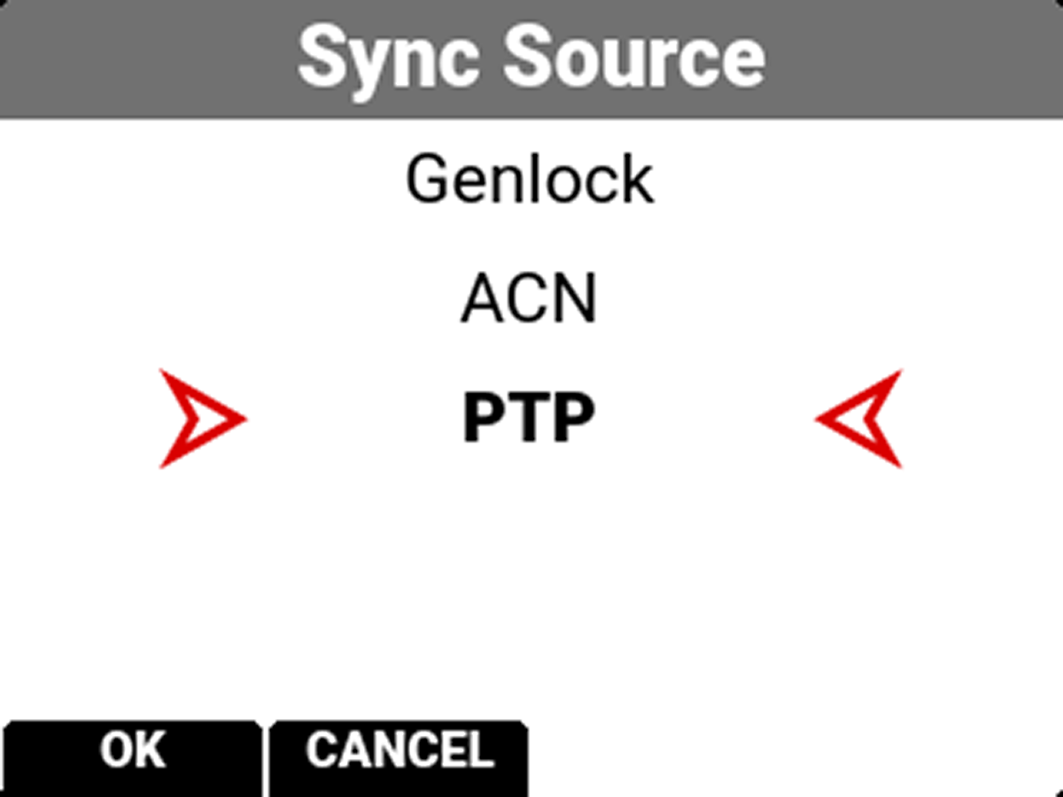
To enable GEN/SYNC PTP, go to Menu>System Settings>Sensor>Sync Source and change it to PTP.
After a few seconds, the GEN/SYNC indicators on the main menu of the camera will go from blank to red to green. Green indicators that the camera sensor is now also synced over PTP.