Monitoring
The camera provides several methods for monitoring the image. These monitoring methods include:
- DSMC3™ RED® Touch 7.0" LCD
- SDI output to a monitor
- RED Control over Wi-Fi to iOS or Android devices
- RED Control over USB-C to iOS or Android devices
- USB-C to Ethernet adapter to a computer
- Live Stream
DSMC3™ RED® Touch 7.0" LCD
The optional DSMC3™ RED Touch 7.0" LCD provides a 1920 x 1200 resolution live image from the camera sensor. By using the Monitoring menu, you can use display guides, exposure tools, focus tools, and a magnified image on this monitor (refer to Top LCD).
SDI Output to a Monitor
The SDI ports provide a 12G SDI signal to allow viewing of the camera image on a 4K SDI monitor. The output signal bit depth is 10-bit 4:2:2.
Use the SDI menus to select the settings for SDI output, Tools, and Guides (refer to SDI 1 / 2).
WARNING: Under certain circumstances, it is possible for an SDI connector to incur damage when connected to an accessory and powered without using shielded cables. RED recommends only using high quality, shielded BNC cables that are rated for 12G-SDI signals and only using shielded power cables for powering SDI accessories.
Make sure power is connected to the SDI accessory at all times before you connect the BNC to the camera. Ungrounded power from SDI accessories can damage the camera’s SDI port. To avoid this possible damage, attach the power source to the accessory before attaching it to the BNC cable. When using RED Approved Third Party battery plates, unplug the BNC cable prior to hot swapping.
When possible, avoid using P-Tap (also known as D-Tap) cables to power accessories. To avoid damage when using P-Tap/D-Tap, it’s imperative that the connect/disconnect sequence (below) is followed precisely.
BNC Attachment Instructions
When attaching SDI accessories:
- Connect a power source to the SDI accessory; power on the SDI accessory.
- Ensure a power source is connected to the camera. This ensures both are grounded prior to connecting the BNC. The camera's power state does not have an impact on SDI attachment sequence.
- Connect the BNC cable to the accessory, then to the camera.
When detaching an accessory mounted to an SDI output, ensure that you remove the BNC connection to the camera before removing power to the SDI device:
- Shutdown the SDI accessory.
- Disconnect the BNC cable from the camera.
- Disconnect the power source from the SDI accessory.
When you need to swap out a battery on an accessory mounted to the camera’s SDI port, you must:
- Shutdown the SDI accessory.
- Disconnect the BNC cable from the camera.
- Replace the battery on the SDI accessory.
- Connect the BNC cable to the camera.
- Power on the SDI accessory.
For more information about SDI safety, refer to Preventing Damage to SDI Outputs.
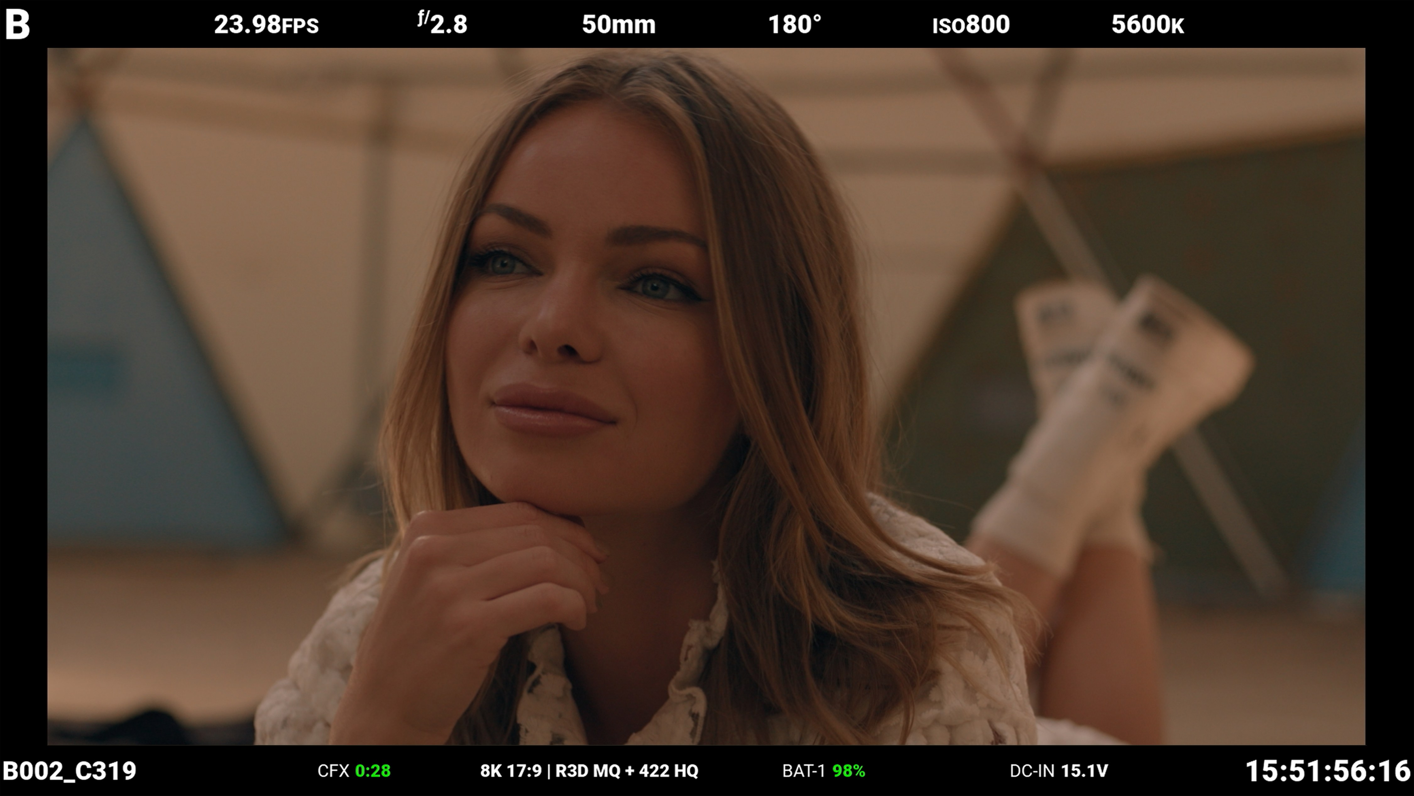
Figure: SDI monitor with SDI Standard Overlay Mode enabled
SDI port specifications:
- Integrated 12G-SDI with 6G-SDI, 3G-SDI, and 1.5G-SDI modes
- 12G-SDI: Up to 4096 × 2160 10-bit 4:2:2 for 60p
- 6G-SDI: Up to 4096 × 2160 10-bit 4:2:2 for 30p
- 3G-SDI: Up to 2048 × 1080 10-bit 4:2:2 for 60p
- 1.5G-SDI: Up to 720p and 1080i 10-bit 4:2:2 for 30p and 24p
- SMPTE Timecode
- HANC metadata
- Up to four (4) channels of 24-bit 48 kHz audio (refer to Audio Source)
You can enable or disable the image magnification, the focus and exposure tools, and the guides displayed on images sent to the SDI monitor by using the SDI menus (refer to SDI 1 / 2).
From the side LCD, navigate to the SDI tools (refer to SDI Page).
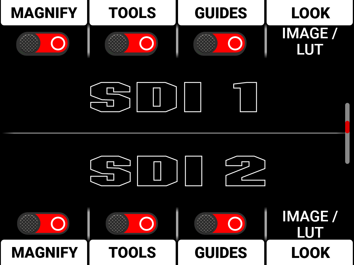
You can enable or disable the following monitoring tools on SDI, (refer to SDI 1 / 2):
- Magnify
- SDI tools
- SDI guides
You can also select the Image / LUT look defined in the Image / LUT menu, or you can select the RWG (REDWideGamutRGB) / Log3G10 Image Processing Pipeline (IPP2) look.
RED Control
RED Control allows you to use Wi-Fi to connect to the camera and send monitor images to iOS and Android devices.
NOTE: You must enable live streaming under MENU > MONITORING > LIVE STREAM to enable the image feed.
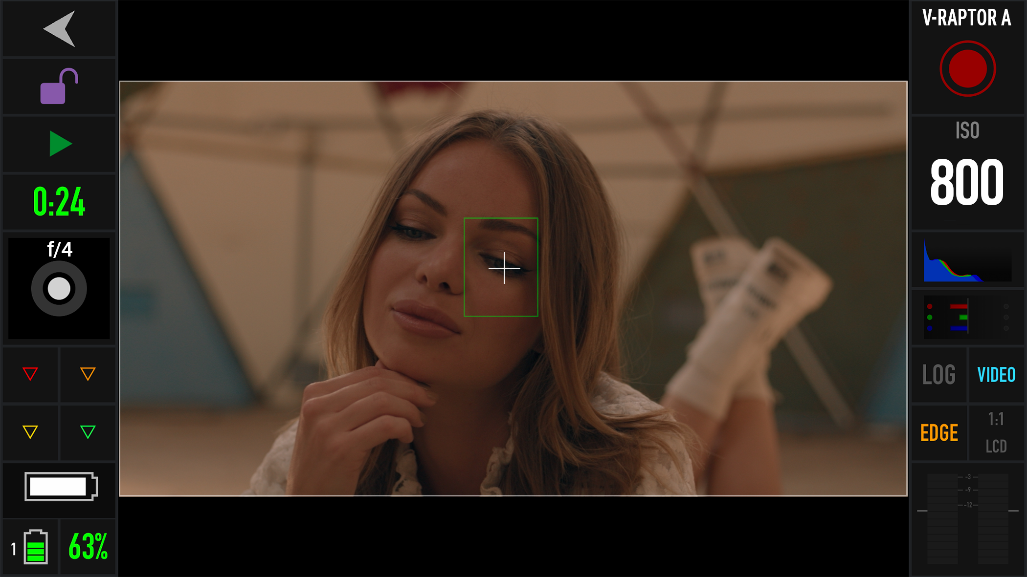
Figure: RED Control phone monitor over Wi-Fi
USB-C
Use a USB-C cable to connect to the camera and send monitor images in real-time to cellular devices using the RED Control app.
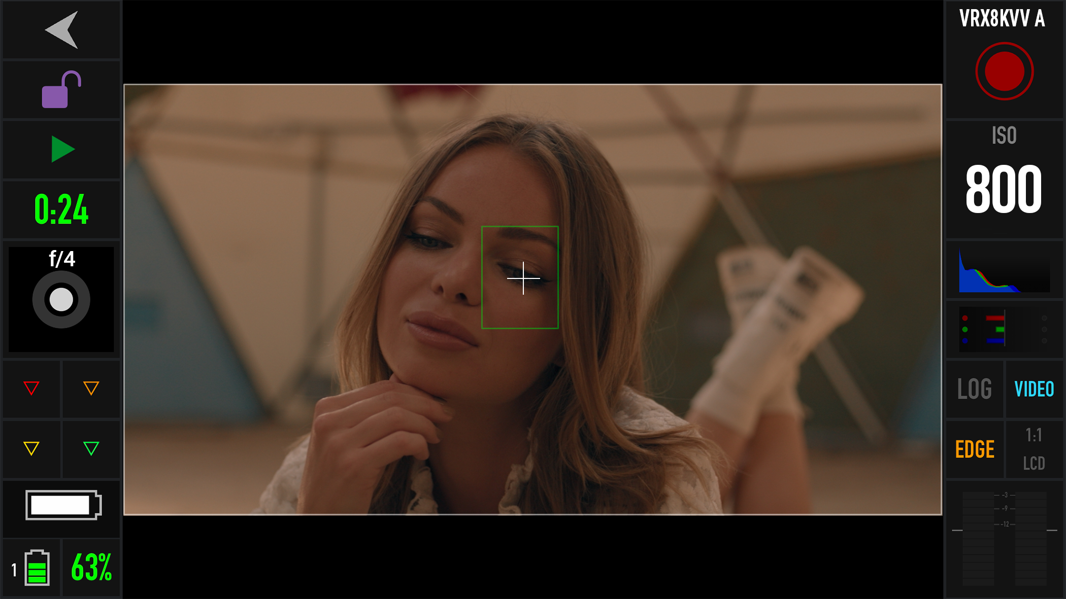
Figure: USB-C connected to an Android cellular phone with the RED Control app
With the use of an Ethernet to USB-C adapter, you can also connect Ethernet devices.
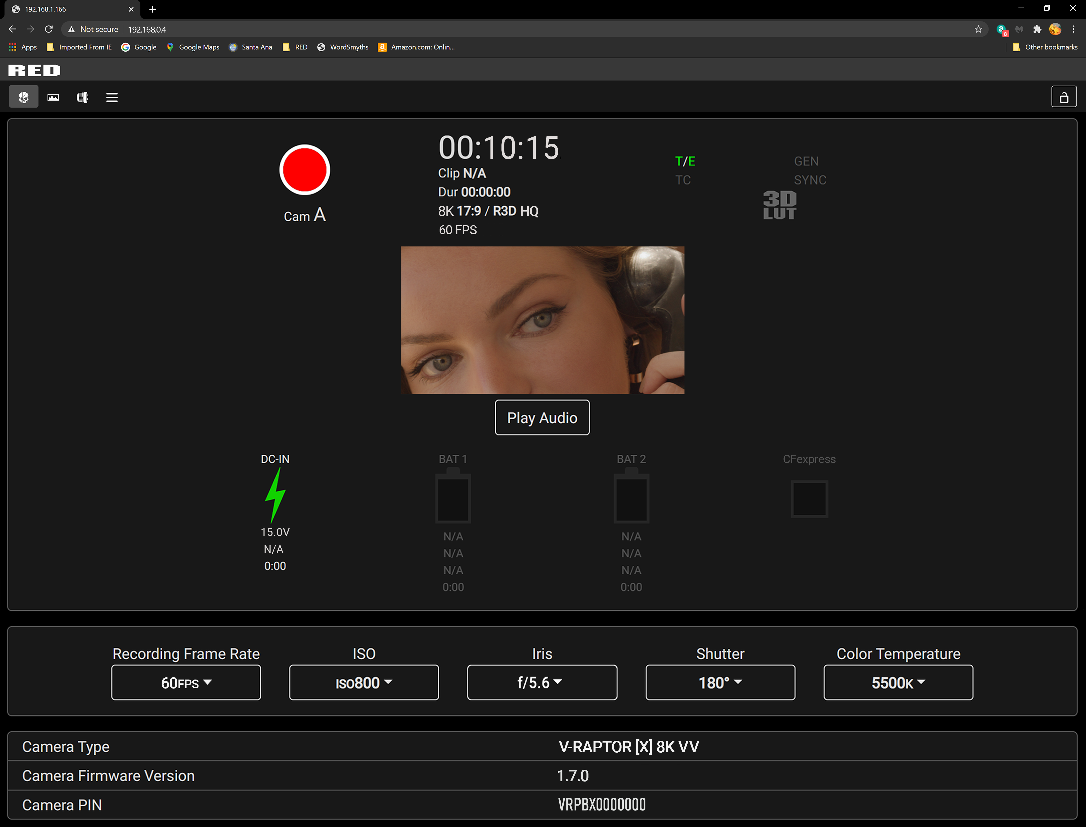
Figure: USB-C connected to an Ethernet web browser
You can add :9090 to the end of the URL in your browser to bring up an image-only feed for remote viewing.
NOTE: You must enable live streaming under MENU > MONITORING > LIVE STREAM to enable the image feed.