V-RAPTOR® Expander Blade
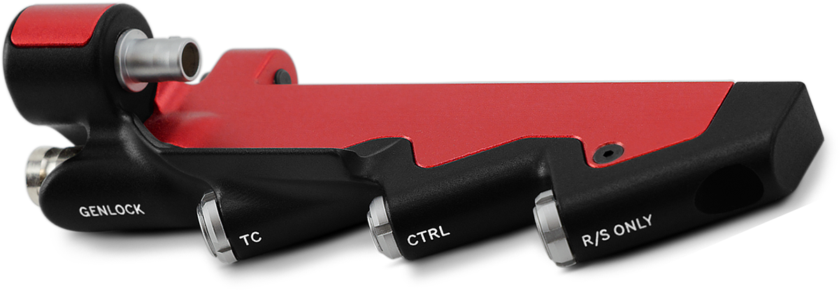
The V-RAPTOR® Expander Blade adds options for video and communication connections including Genlock (BNC), Timecode (5-Pin), RED CTRL (4-Pin), and R/S (Run/Stop) 3-Pin.
NOTE:
- The 3-Pin Fischer R/S port does not provide power, it is for trigger control only.
- The V-RAPTOR camera plate is RRS Dovetail Standard (38 mm).
Genlock 75 Ohm Male BNC Connector
")
Figure: Front Face of the Genlock male BNC Connector (looking at the front of the connector).
|
pin |
signal |
description |
Direction |
|---|---|---|---|
|
Center |
Sync |
SMPTE ST 274 RS 170A Tri-Level Sync |
In |
|
Shell |
Ground |
Common ground (camera ground) |
N/A |
NOTE: Mating connector is standard 75 ohm female BNC connector.
Timecode LEMO 5-Pin 0B Connector

Figure: Front face of Timecode 0B Connector (looking at the front of the connector).
|
pin |
signal |
description |
Direction |
|---|---|---|---|
|
1 |
GROUND |
Camera ground |
NA |
|
2 |
Timecode In |
Timecode input - SMPTE single ended |
In |
|
3 |
NA |
No connection |
NA |
|
4 |
+5 V Out |
+5 V out, 200 mA max |
Out |
|
5 |
Timecode Out |
SMPTE 12 M Timecode output |
Out |
NOTE: Mating connector is LEMO FHG.0B.305.CLAD.
Control (CTRL) LEMO 4-Pin 00B Connector
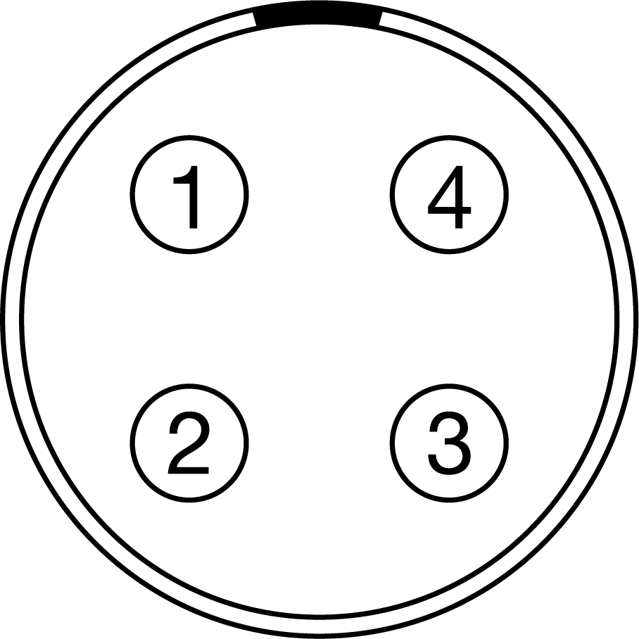
Figure: Front face of female 4-Pin 00B CTRL connector (looking at the front of the connector).
The female LEMO 4-Pin 00B CTRL connector supports RS-232 remote control for 3D camera communication and third-party metadata ingest applications.
For more information about controlling the camera using RS-232, download the R.C.P.™ SDK, available at www.red.com/developers.
|
PIN |
|
SIGNAL |
|
Description |
|
Direction |
|---|---|---|---|---|---|---|
|
1 |
|
GROUND |
|
Common ground |
|
N/A |
|
2 |
|
232 RX |
|
RS-232 receive |
|
In |
|
3 |
|
GPO |
|
Set the General Purpose Out (GPO) to send a tally signal, or to send a recording frame rate signal (3.3V TTL) |
|
Out |
|
4 |
|
232 TX |
|
RS-232 transmit |
|
Out |
NOTE: Mating connector is LEMO FGG.00.304.CLAD.
Compatible Cable
- 790-0187, 790-0648: 4-Pin 00B-to-Flying Lead
- White: Ground
- Yellow: RS-232 receive
- Blue: Shutter/sync, general purpose output
- Red: RS-232 transmit
- Black: Shield
Fischer 3-Pin OL Female R/S Connector
")
Figure: Front face of the female Fischer R/S connector (looking at the front of the connector).
|
pin |
signal |
description |
Direction |
|---|---|---|---|
|
1 |
Ground |
Power return (camera ground) |
N/A |
|
2 |
None |
No connection |
N/A |
|
3 |
R/S |
Pull to ground (Pin 1) to start/stop record1 |
In |
- The signal path includes a resistor pulling the signal high, which is designed to work with a closure switch connected to ground.
NOTE: Mating connector is a standard male Fischer 3-Pin OL connector.
CONTACT CLOSURE STYLE TRIGGER BUTTON CIRCUIT (R/S)
The diagram below shows the contact closure style trigger button circuit on the R/S connector.

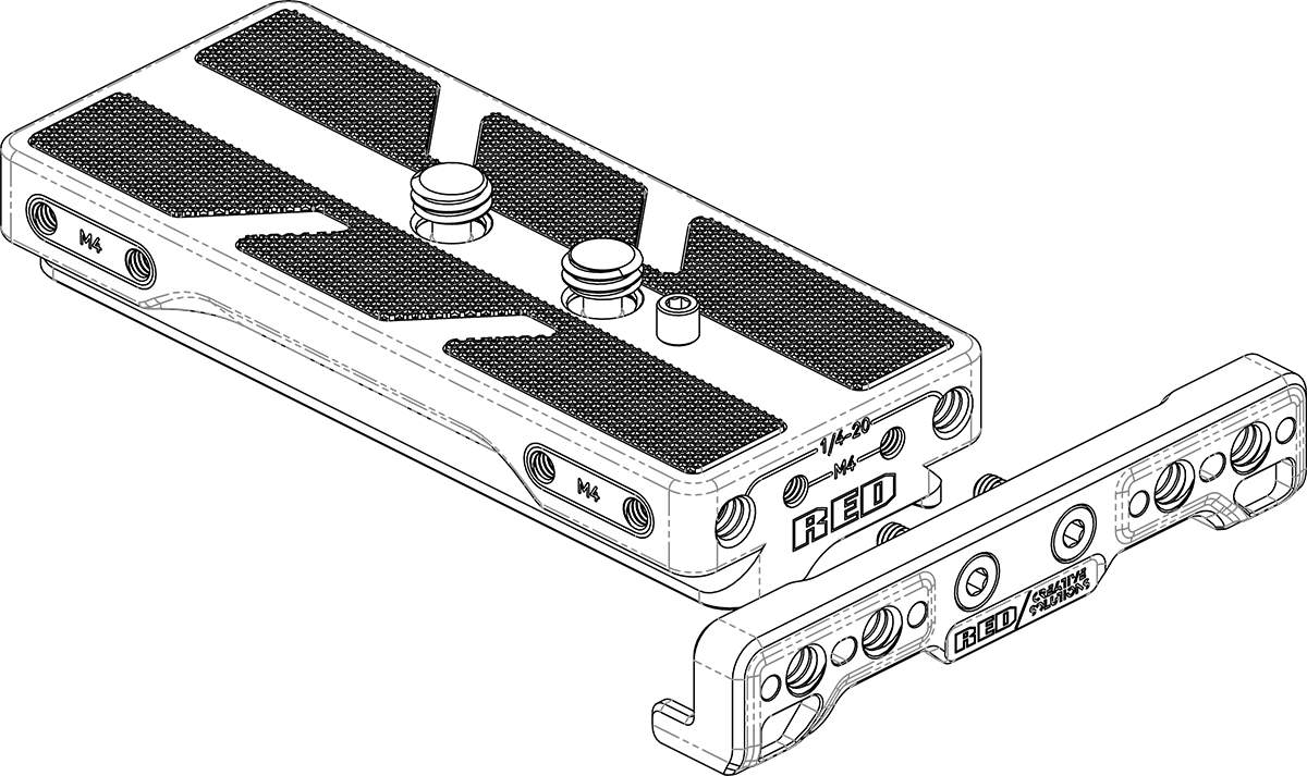
To attach the Expander Blade to the camera, the following are required (included with purchase of V-RAPTOR® Expander Blade):
- V-RAPTOR® Expander Blade
- V-RAPTOR® Arca Plate (also included in the V-RAPTOR® Quick Release Platform Pack)
- Anti-Tip Plate (optional)
- Attach the Arca plate to the bottom of the camera. This plate provides two secure mounting points for the to Expander Blade.
- Line up the Expander Blade's 9-Pin connector with the camera's 9-Pin EXT connector and gently slide the Expander Blade towards the camera until the connector is fully seated.
- Partially screw the front Expander Blade M4 screw to the Arca Plate. Line the rear Expander Blade M4 screw up with the correctly and fully tighten this screw. Return to the front M4 screw to fully tighten.
NOTE: Without this plate, the Expander Blade cannot be secured to the body, likely resulting in damage to the camera’s 9-Pin EXT port and to the Expander Blade's 9-Pin connector.
Optionally, you can attach the Anti-Tip Plate to the front of the Arca Plate to prevent the camera from tipping over when resting the camera with the Arca Plate on a hard flat level surface.
To attach the Anti-Tip Plate, ensure the correct orientation of the Anti-Tip Plate & then align the M4 screws with the M4 mounting holes on the front of the Arca Plate (this plate can only be attached at the front of the camera). Tighten down the M4 screws until tight.
For issues or troubleshooting, contact support@cs.inc.