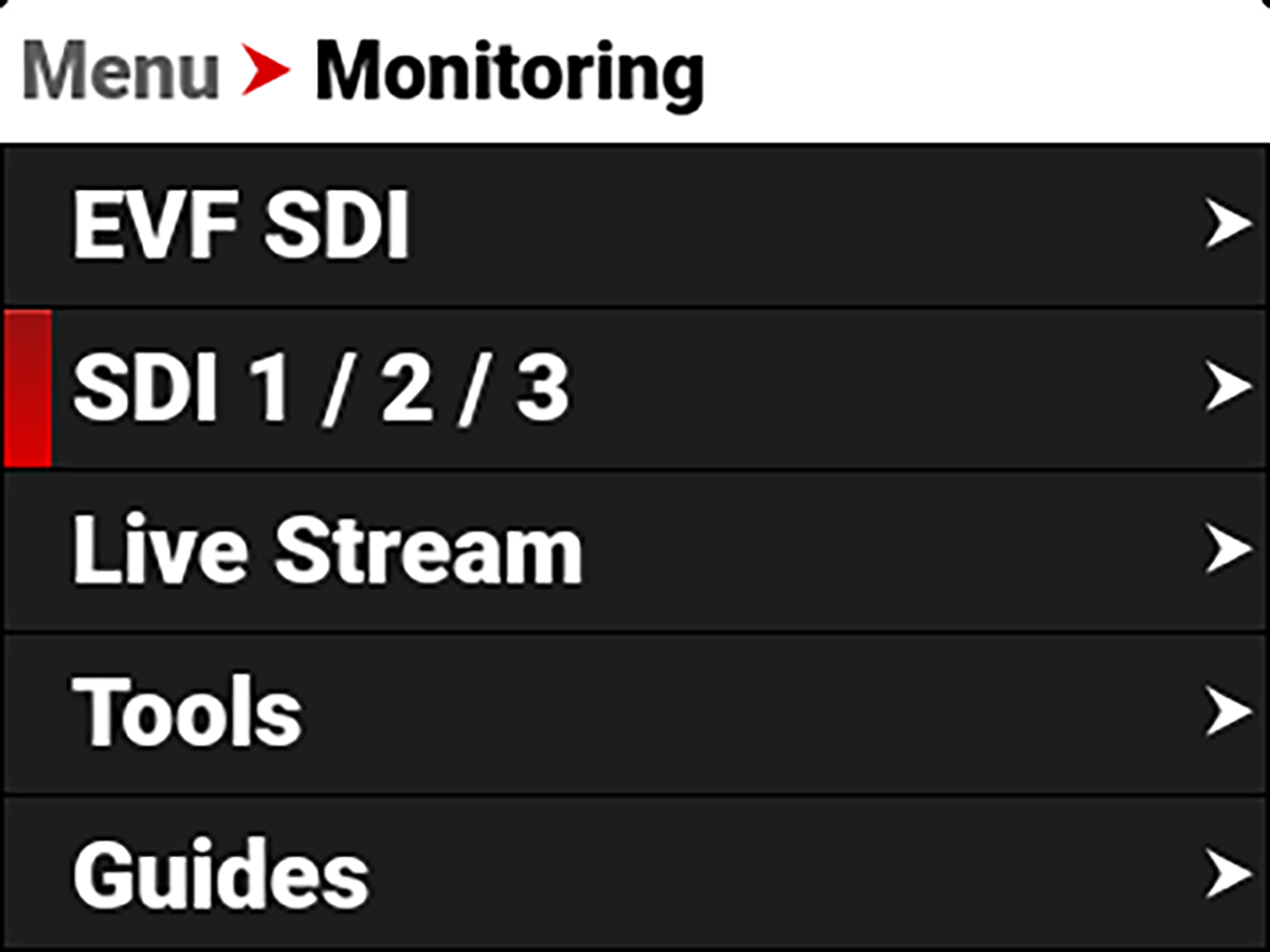
SDI 1 / 2 / 3
Use SDI 1 / 2 / 3 to configure the settings on SDI ports 1,2, and 3.
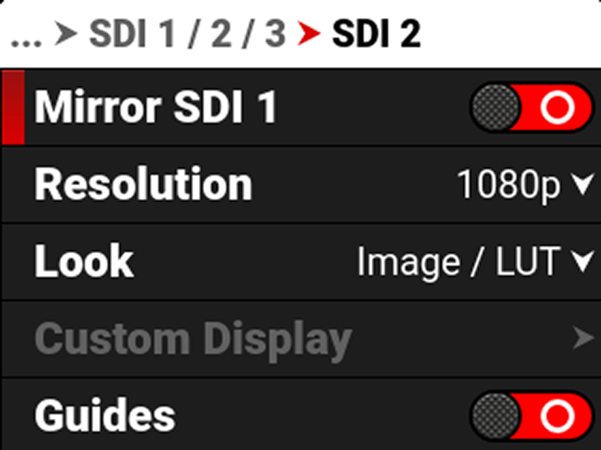
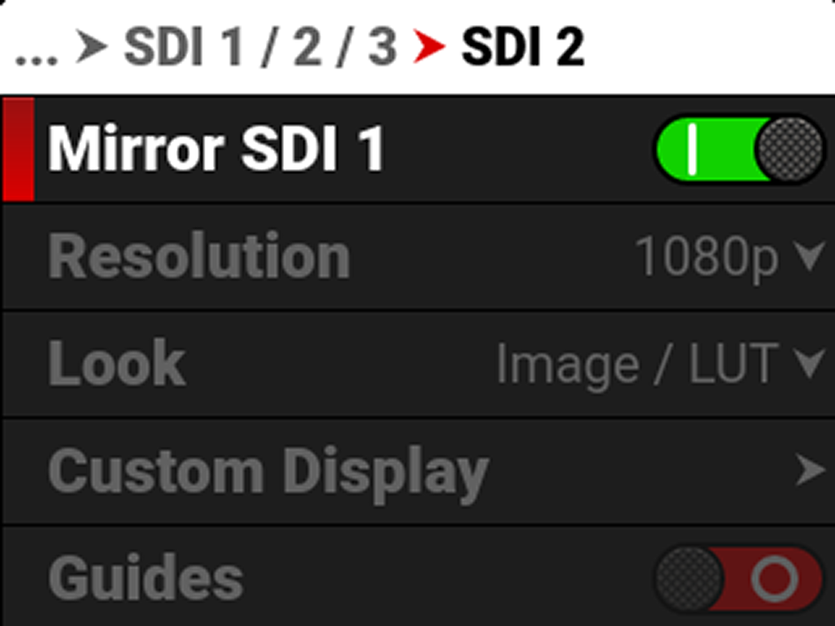
You can quickly configure SDI 2 to match SDI 1 by selecting Mirror SDI 1 on the SDI 2 menu:
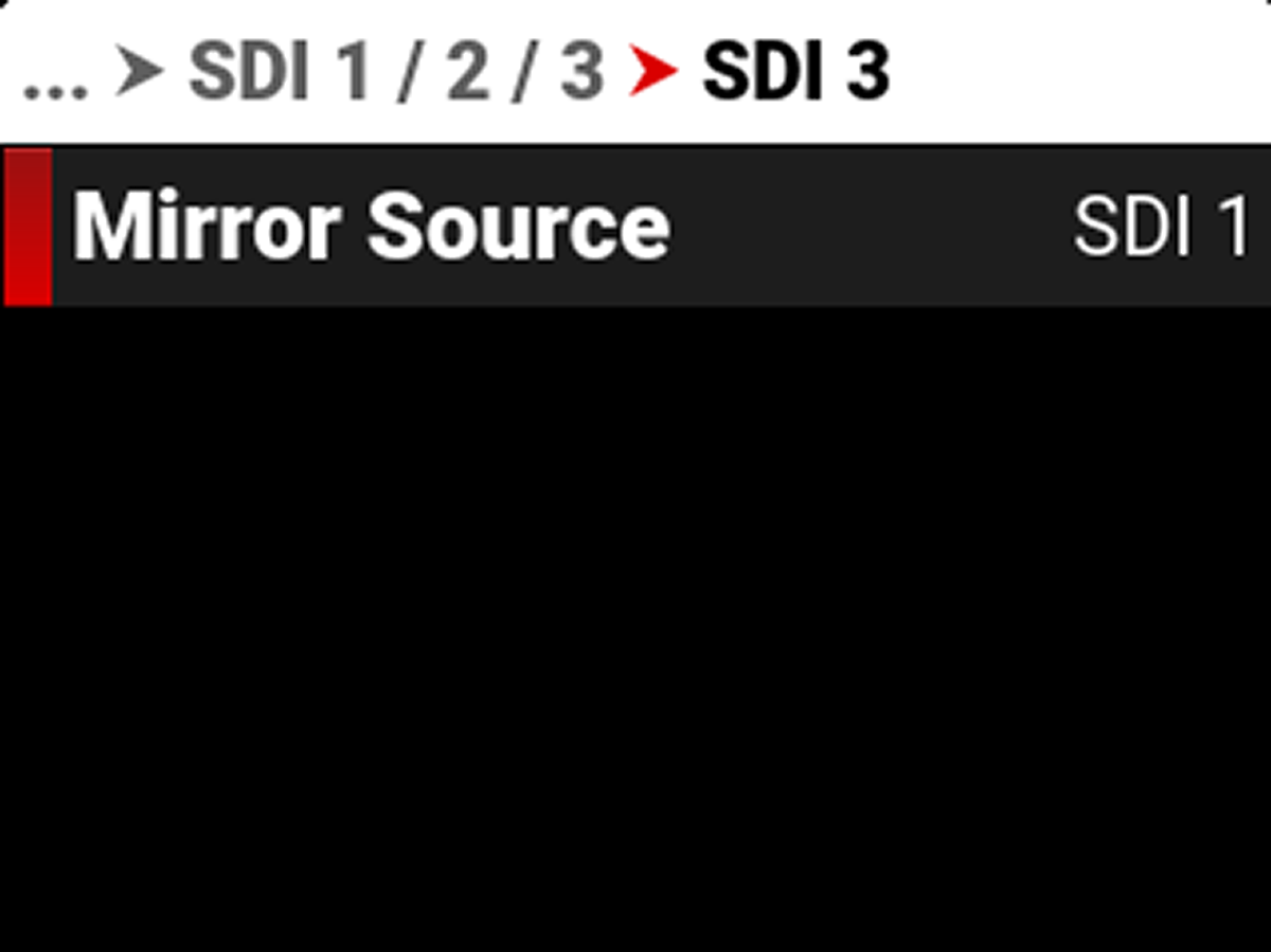
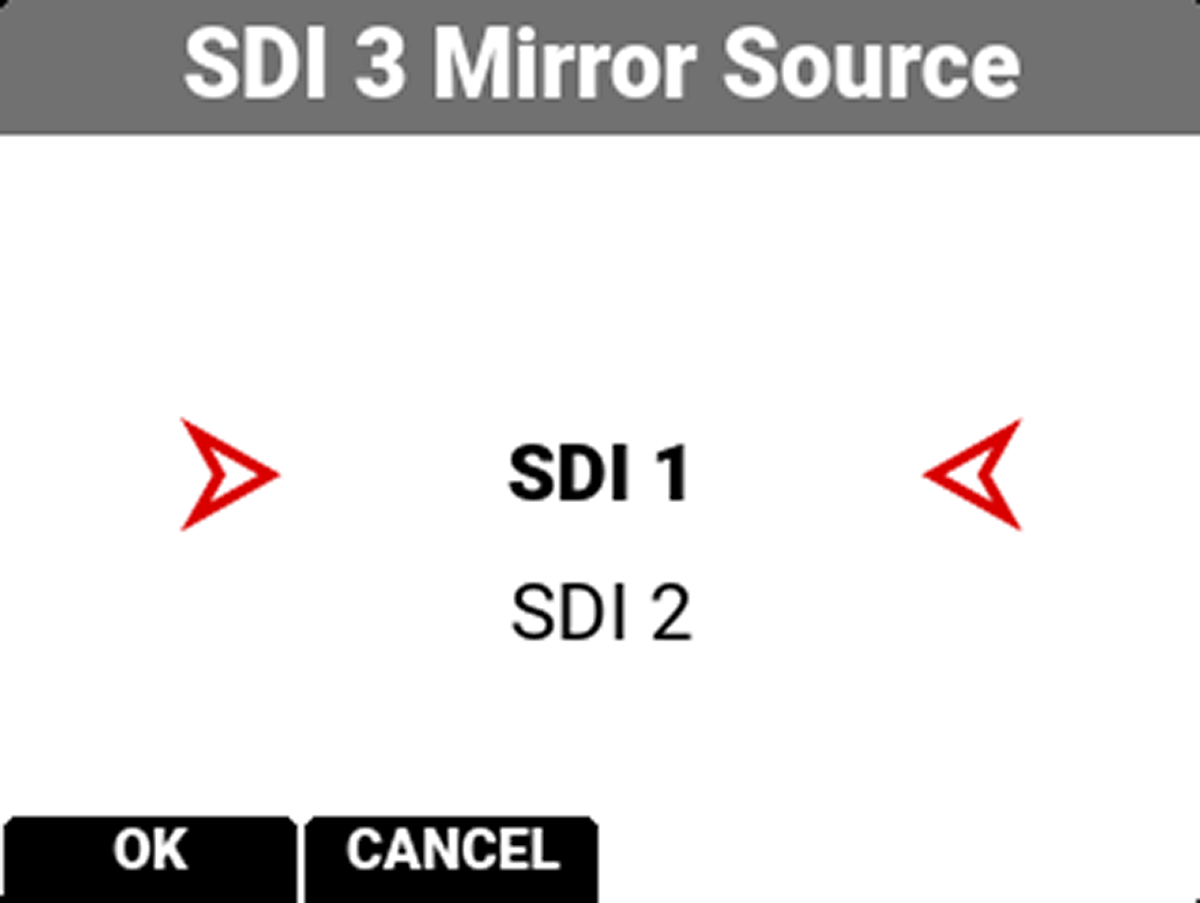
SDI 3 can mirror SDI 1 or 2:
The SDI 1 and 2 port settings you can configure include:
|
Item |
Details |
|---|---|
|
Select the SDI port frequency |
|
|
Select the Phantom Track to display on the SDI port (when enabled) |
|
|
Select the SDI port resolution |
|
|
Set the look of the monitor to RWG/Log3G10, Image/LUT, or Custom Display |
|
|
Configure the look of the monitor independently of other monitor pipelines |
|
|
Enable or disable the monitor guides |
|
|
Enable or disable the monitor tools |
|
|
Manage the monitor overlay settings |
|
|
Magnify the monitor image |
|
|
Select the area of the image to magnify |
|
|
Select the opacity of the overlay |
|
|
Flip and mirror the image output to the monitor |
WARNING: Under certain circumstances, it is possible for an SDI connector to incur damage when connected to an accessory and powered without using shielded cables. RED recommends only using high quality, shielded BNC cables that are rated for 12G-SDI signals and only using shielded power cables for powering SDI accessories.
Make sure power is connected to the SDI accessory at all times before you connect the BNC to the camera. Ungrounded power from SDI accessories can damage the camera’s SDI port. To avoid this possible damage, attach the power source to the accessory before attaching it to the BNC cable. When using RED Approved Third Party battery plates, unplug the BNC cable prior to hot swapping.
When possible, avoid using P-Tap (also known as D-Tap) cables to power accessories. To avoid damage when using P-Tap/D-Tap, it’s imperative that the connect/disconnect sequence (below) is followed precisely.
BNC Attachment Instructions
When attaching SDI accessories:
- Connect a power source to the SDI accessory; power on the SDI accessory.
- Ensure a power source is connected to the camera. This ensures both are grounded prior to connecting the BNC. The camera's power state does not have an impact on SDI attachment sequence.
- Connect the BNC cable to the accessory, then to the camera.
When detaching an accessory mounted to an SDI output, ensure that you remove the BNC connection to the camera before removing power to the SDI device:
- Shutdown the SDI accessory.
- Disconnect the BNC cable from the camera.
- Disconnect the power source from the SDI accessory.
When you need to swap out a battery on an accessory mounted to the camera’s SDI port, you must:
- Shutdown the SDI accessory.
- Disconnect the BNC cable from the camera.
- Replace the battery on the SDI accessory.
- Connect the BNC cable to the camera.
- Power on the SDI accessory.
For more information about SDI safety, refer to Preventing Damage to SDI Outputs.
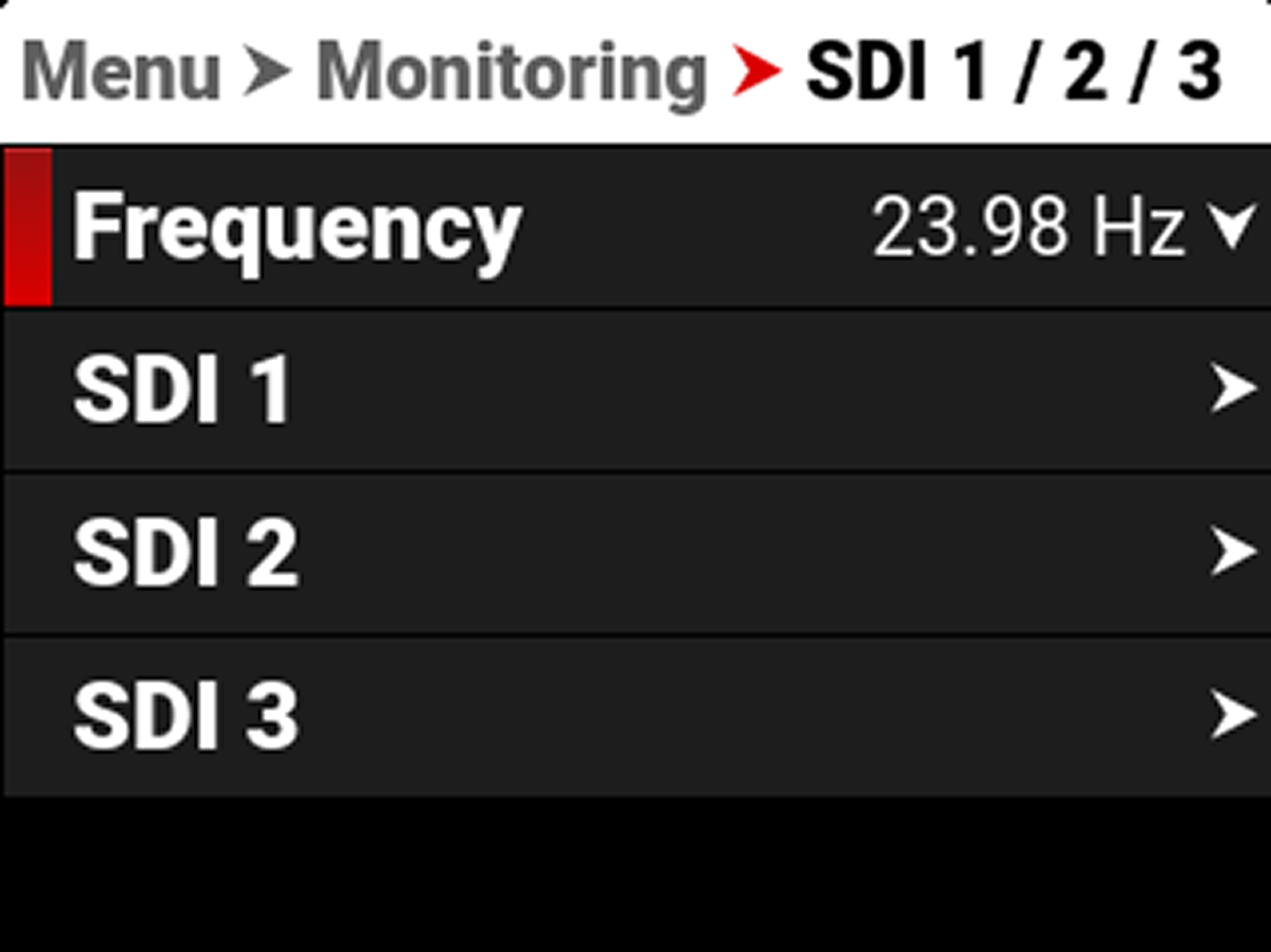
Frequency
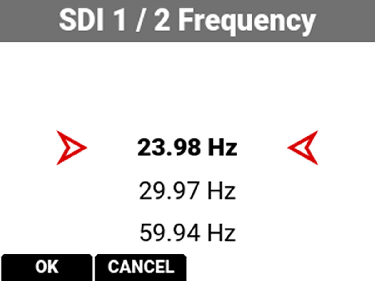
Use Frequency to select one of the following SDI port frequency settings:
• 23.98 Hz
• 29.97 Hz
• 59.94 Hz
NOTE: The camera uses the selected Project Frame Rate frequency by default.
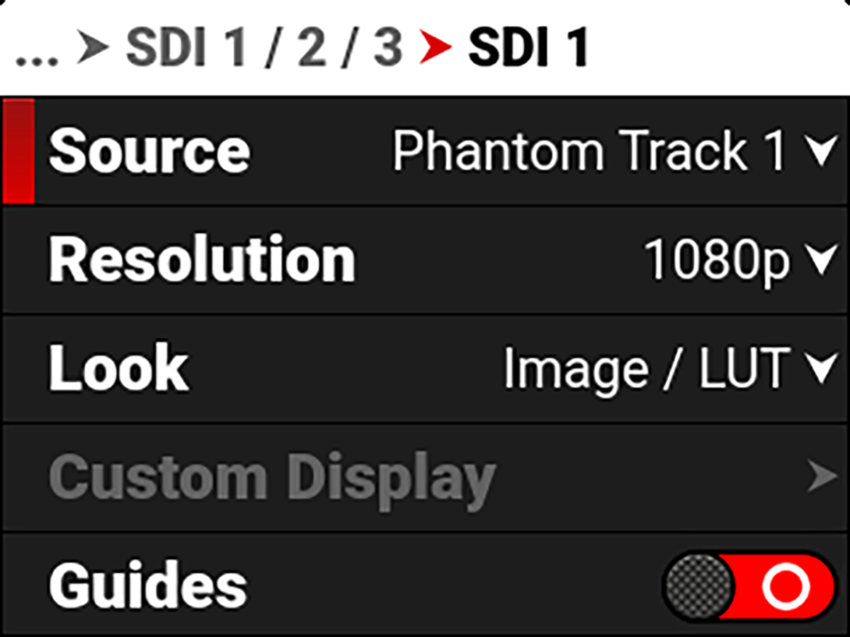
Source
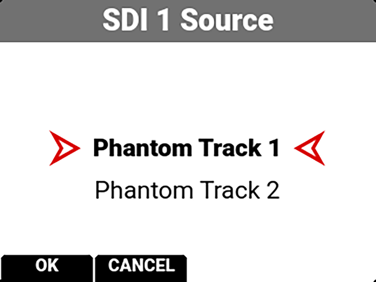
When you enable Phantom Track Recording mode in the Project Settings menu, the Source option is added to the SDI menu. You can use the Source option to select which Phantom track you want to display on the selected SDI port.
Resolution
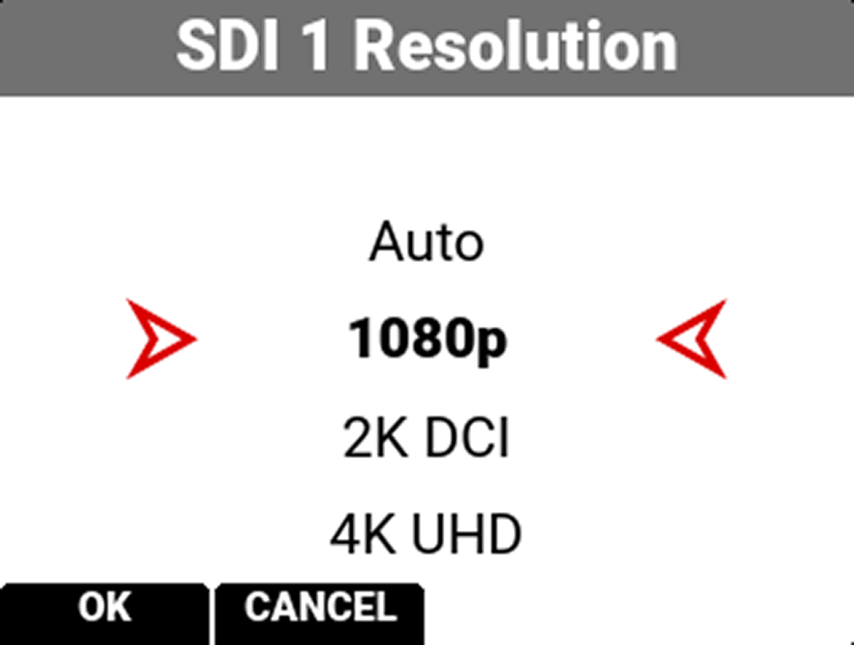
Use resolution to select one of the following SDI port resolution settings:
• Auto
• 1080p (default)
• 2K DCI
• 4K UHD
• 4K DCI
The resolution selected here controls the SDI output resolution of the preview page.
Scaling Preview
When monitoring in 1080p or 4K UHD while capturing in a 17:9 format, the entire 17:9 image will be down-scaled to the 16:9 aspect ratio of 1080p or 4K UHD. Small black bars will only appear on the top and bottom of the frame in the monitor path and not on the recorded image.
Look
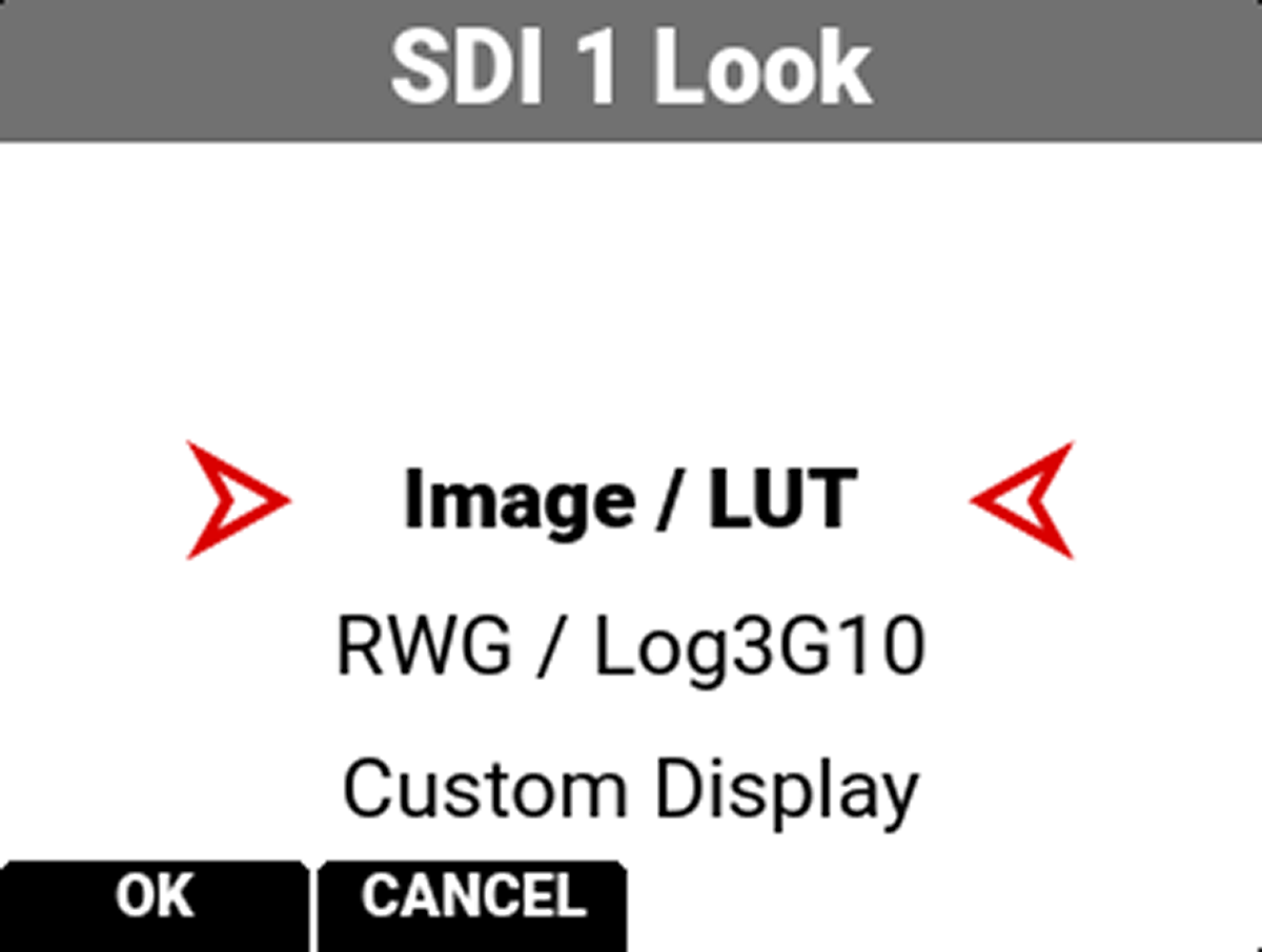
You can select the look of the image preview signal sent to the SDI port.
The selections include:
• Image / LUT (default)
• REDWideGamutRGB / Log3G10
• Custom Display (enables the Custom Display menu)
Custom Display
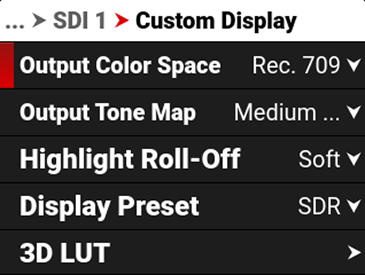
Use Custom Display to configure the SDI independently of the camera's Image / LUT settings or other monitor output configurations.
The camera saves the LUT applied here as a sidecar file alongside the R3D or ProRes file. The saved file uses the format sdi#_LUT Name.cube.
Refer to Image / LUT Menu for more information about how to use the Image/LUT settings and menus.
Guides
Use Guides to enable or disable the viewing of guides. You can enable and disable guides by pressing SEL to toggle Guides to the right (green / enabled) and to the left (red / disabled).


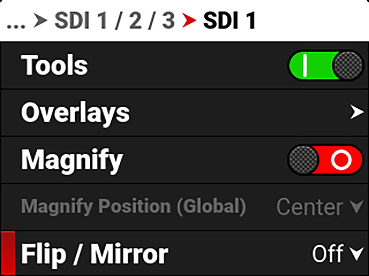
Tools
Use Tools to enable or disable the viewing of tools. You can enable and disable tools by pressing SEL to toggle Tools to the right (green / enabled) and to the left (red / disabled).


Overlays
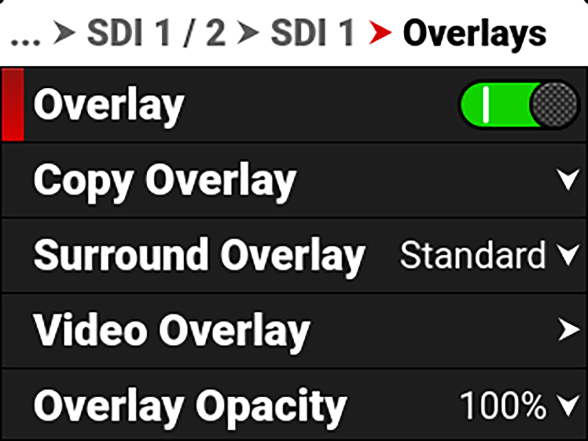
Use Overlays to manage the SDI overlay settings. These settings include:
|
Item |
Details |
|---|---|
|
Overlay |
Enable or disable the SDI overlay display |
|
Copy an overlay from or to SDI 1 and SDI 2 |
|
|
Select the overlay surround type |
|
|
Manage the video overlay display values |
|
|
Select the opacity of the overlay |
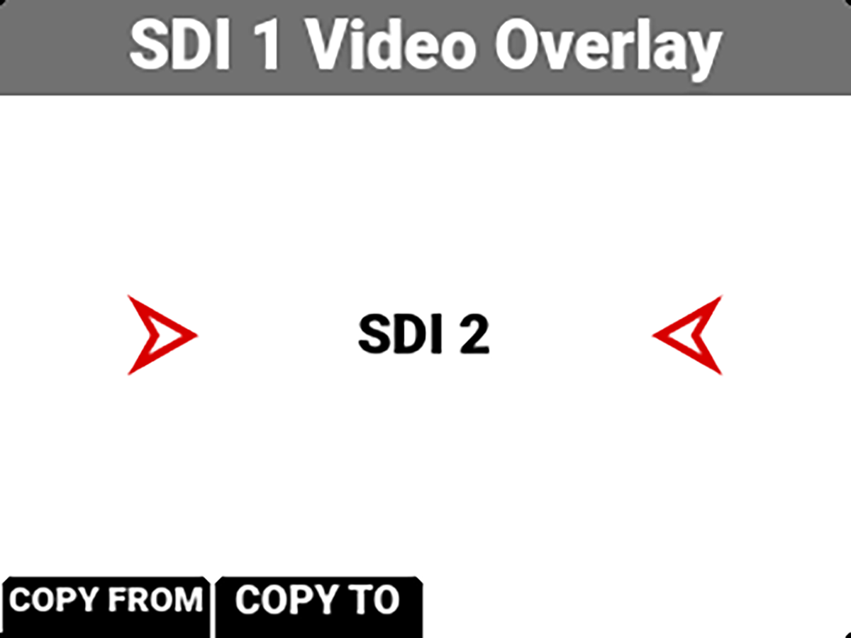
Copy Overlay
Use Copy Overlay to copy an overlay from or to the other SDI port.
Surround Overlay
Use SDI Surround Overlay to select the overlay surround type you want to use for the SDI display. You can select one of the following SDI port overlay modes:
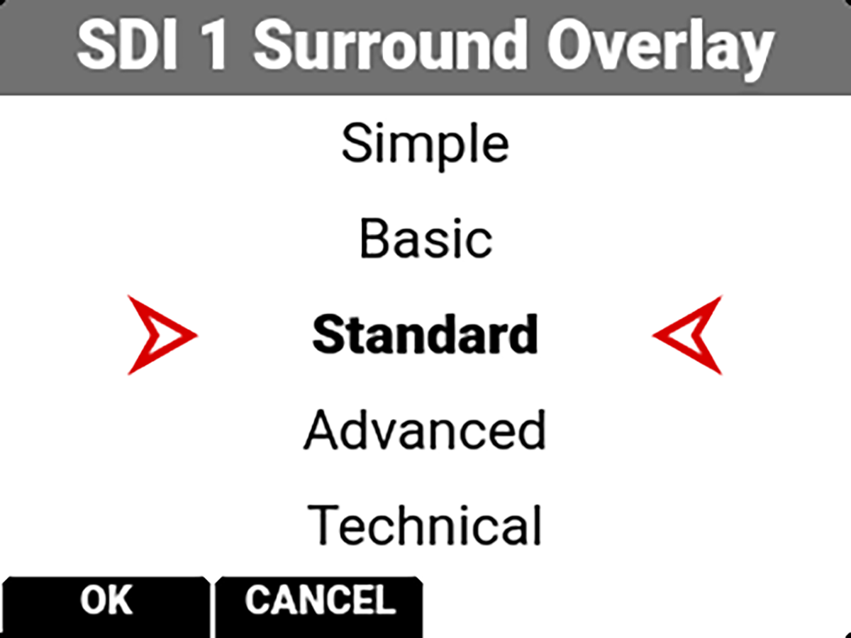
 Simple (refer to Simple Mode)
Basic (refer to Basic Mode)
Standard (refer to Standard Mode)
Advanced (refer to Advanced Mode)
Technical (refer to Technical Mode)
Simple Mode
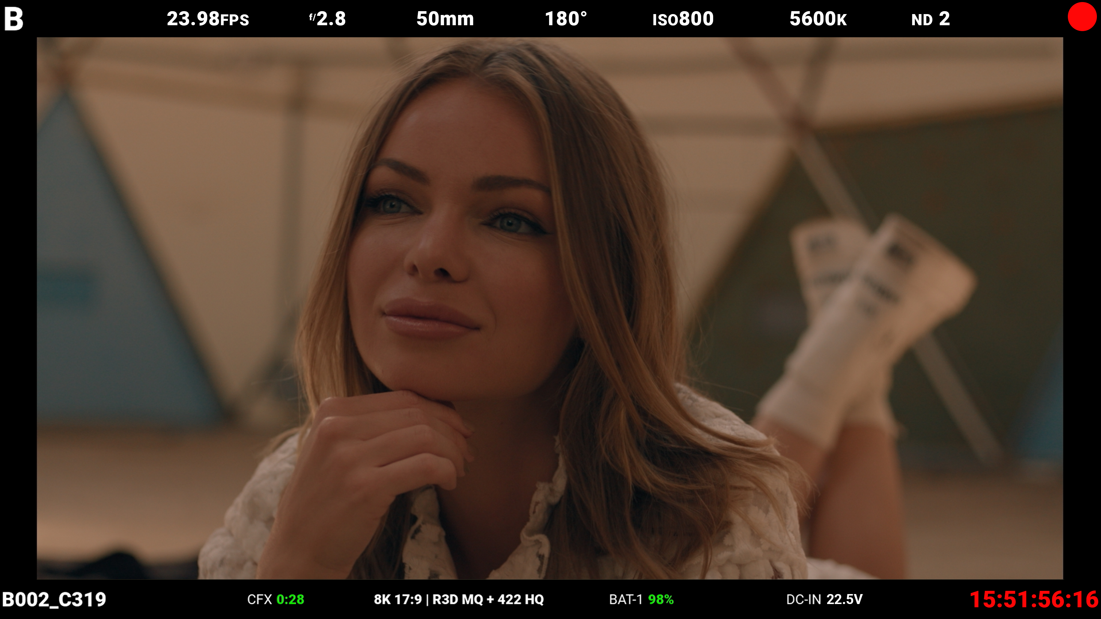
Simple mode displays the clip name and the current Timecode. When the camera is recording, the Timecode turns red, and a red dot appears in the top right corner.
Basic Mode
Basic mode displays the following:
- Clip Name
- CFexpress Time Remaining (at the current settings)
- Timecode
- Battery percentage remaining (at the current settings)
- DC-IN
When the camera is recording, the Timecode turns red, and a red dot appears in the top right corner.
Standard Mode
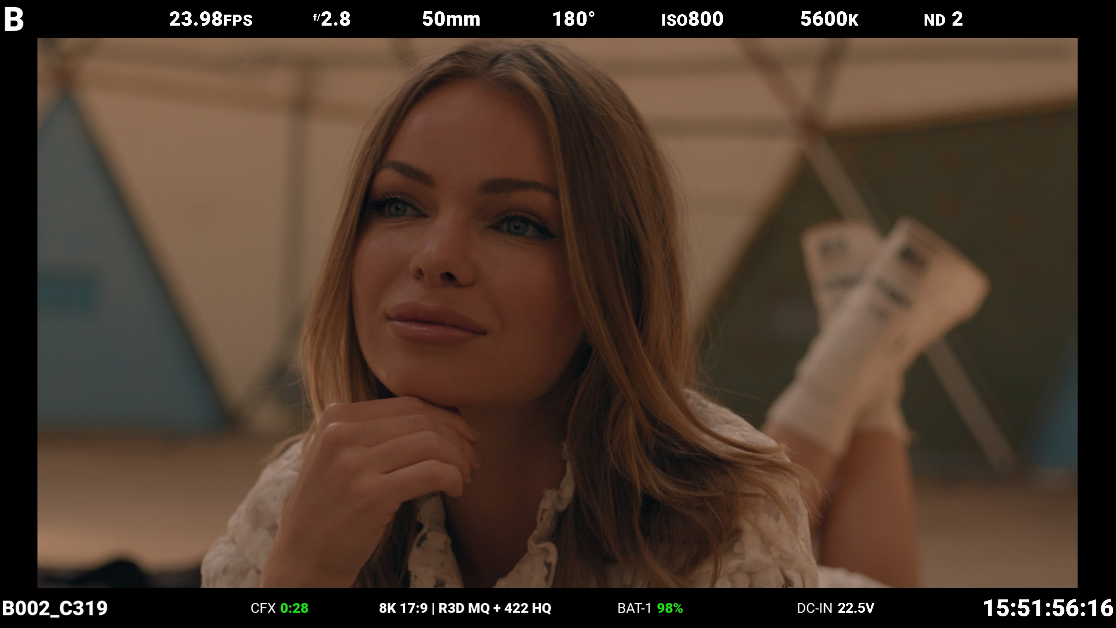
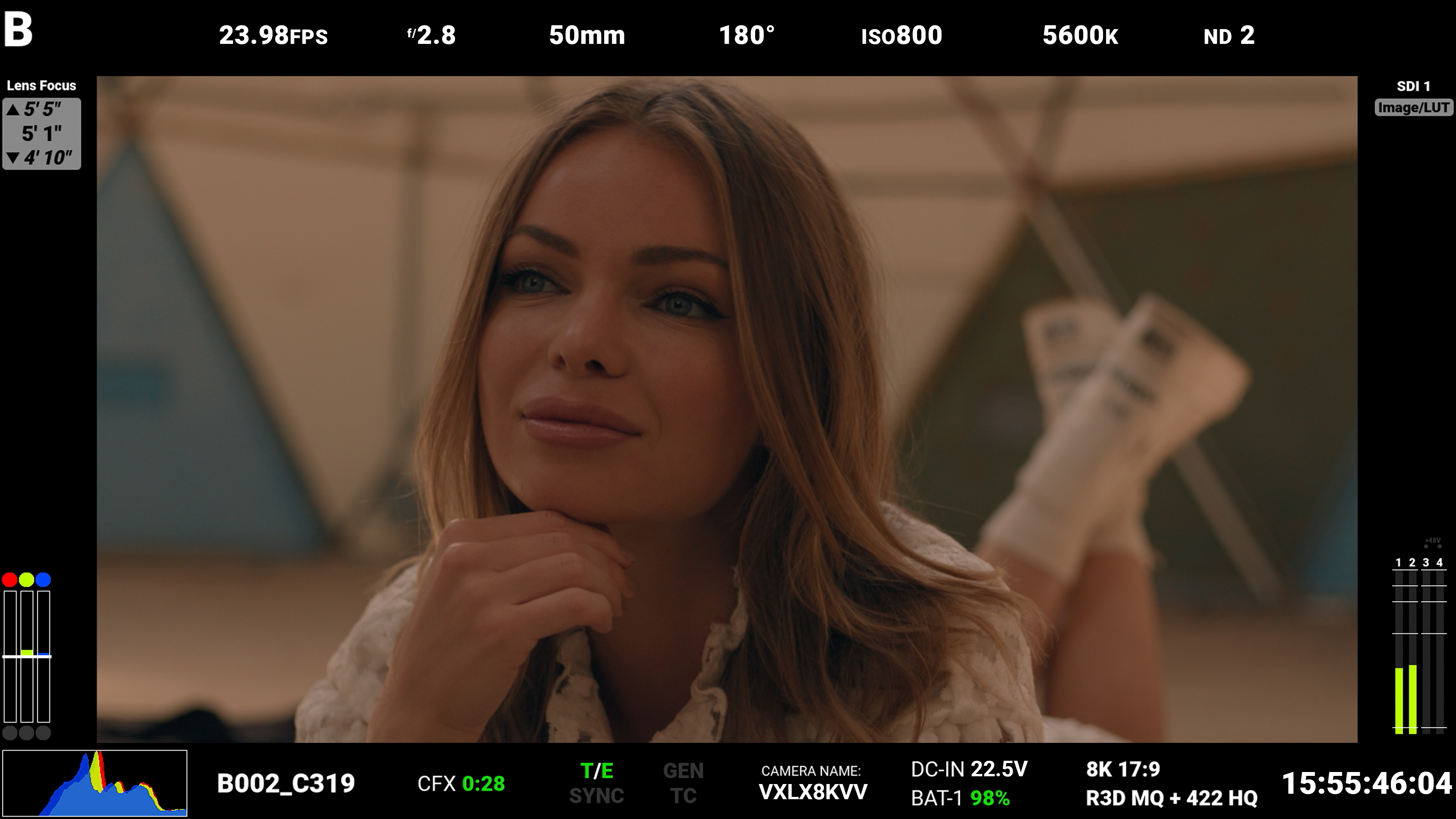
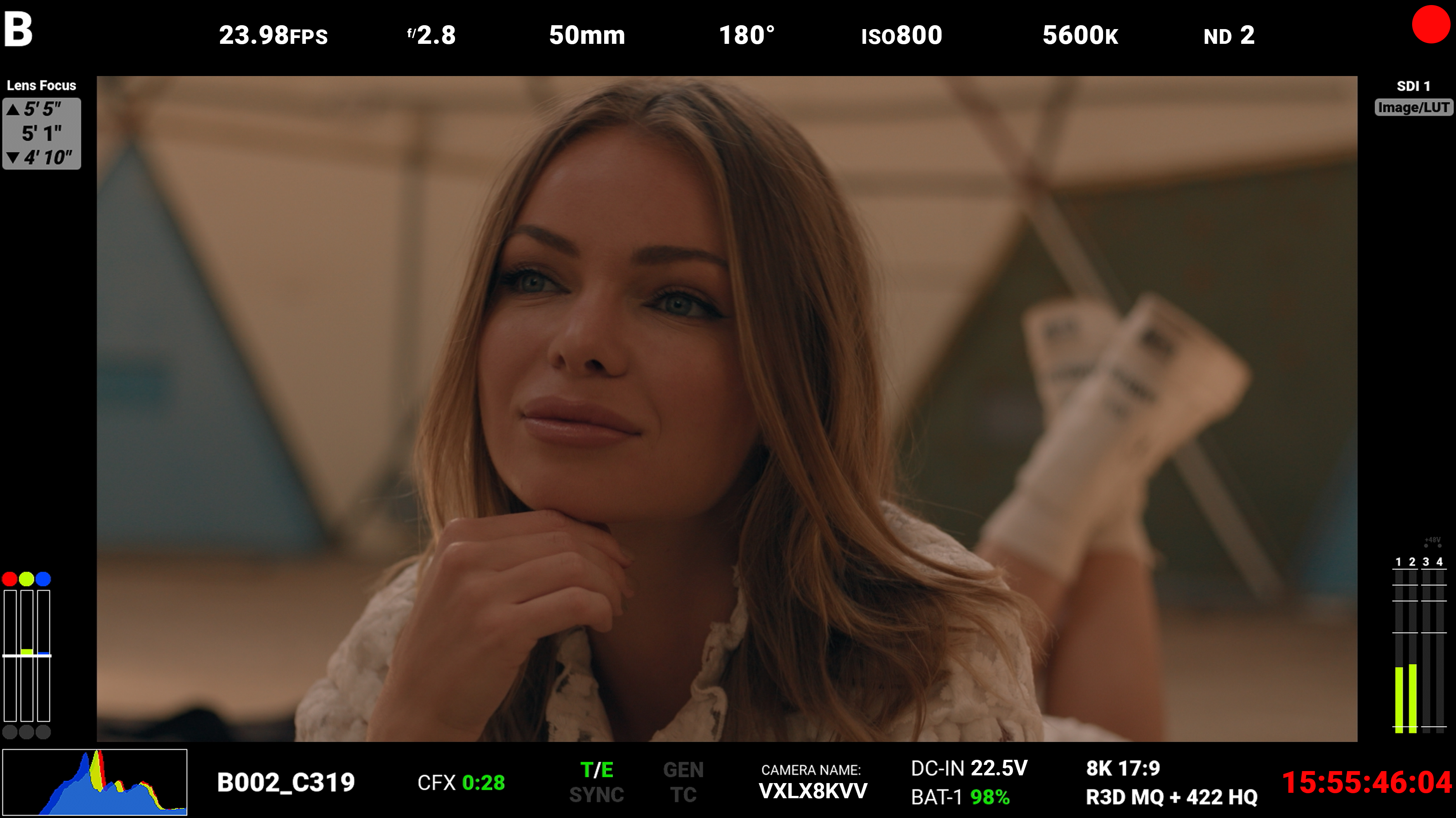
Standard mode displays the following:
|
Top |
Bottom |
|
|
• Camera ID • Recording Frame Rate • f-Stop • Focus Length • Shutter Angle • ISO • White Balance • ND |
• Clip Name • CFexpress Time Remaining • Format, File Type, Rate • Battery • DC-IN • Timecode |
Lens items such as Focal Length and f-Stop will adaptively display depending on whether the lens data is available.
When the camera is recording, the Timecode turns red, and a red dot appears in the top right corner.
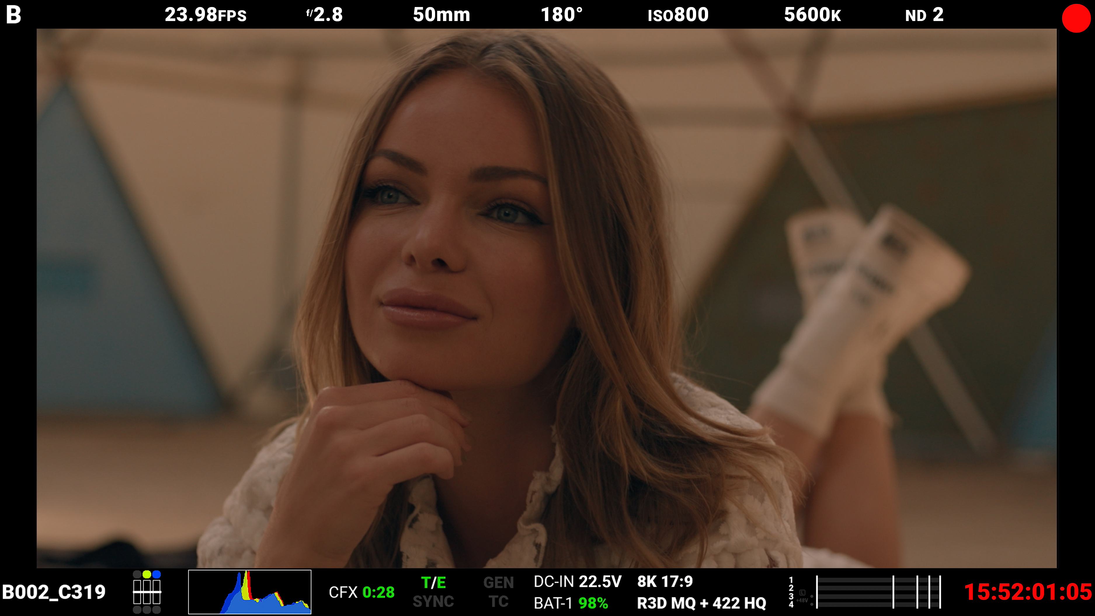
Advanced Mode
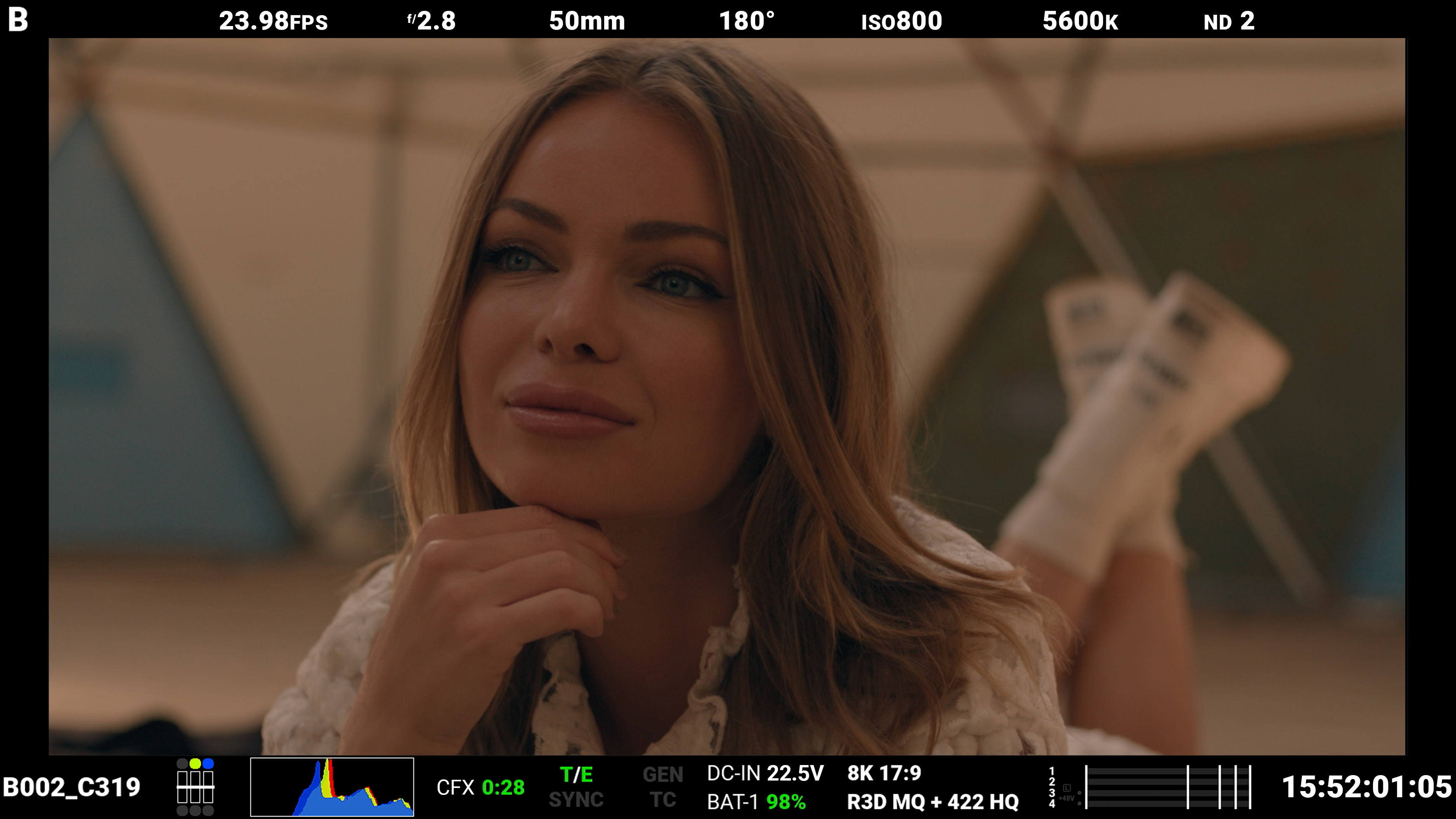
Advanced mode displays the following:
|
Top |
Bottom |
|
|
|
• Camera ID • Recording Frame Rate • f-Stop • Focus Length • Shutter Angle • ISO • White Balance • ND |
• Clip Name • Exposure Meter • Histogram • CFexpress Time Remaining
• Temperature / Exposure |
• Timecode, Genlock, Synch • DC-In, Battery • Format, File Type, Rate • VU Meter • Timecode |
When the camera is recording, the Timecode turns red, and a red dot appears in the top right corner.
Technical mode displays the following:
|
Top |
Bottom |
|
|
|
• Camera ID • Recording Frame Rate • f-Stop • Focus Length • Shutter Angle • ISO • White Balance • ND • SDI Port • Look |
• Exposure Meter • Histogram • Clip Name • CFexpress Time Remaining
• Temperature / Exposure • Timecode, Genlock, Synch • Camera Name • DC-In, Battery |
• Format, File Type, Rate • Timecode • VU Meter |
When the camera is recording, the Timecode turns red, and a red dot appears in the top right corner.
Video Overlay
Use Video Overlay to manage the video overlay display values.
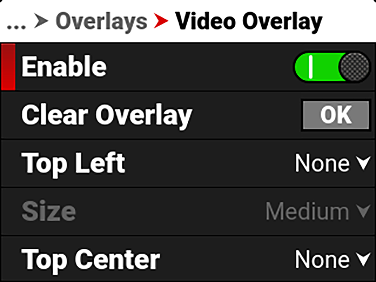
The Video Overlay display value management settings include:
|
Item |
Details |
|---|---|
|
Enable |
Enable or disable video value management |
|
Clear all of the settings from the SDI video overlay |
|
|
Select the location and value for the SDI video overlay values |
|
|
Select the size for the SDI video overlay values |
Clear Overlay
Use Clear Overlay to clear the video overlay values from the SDI display.
![]()
Location
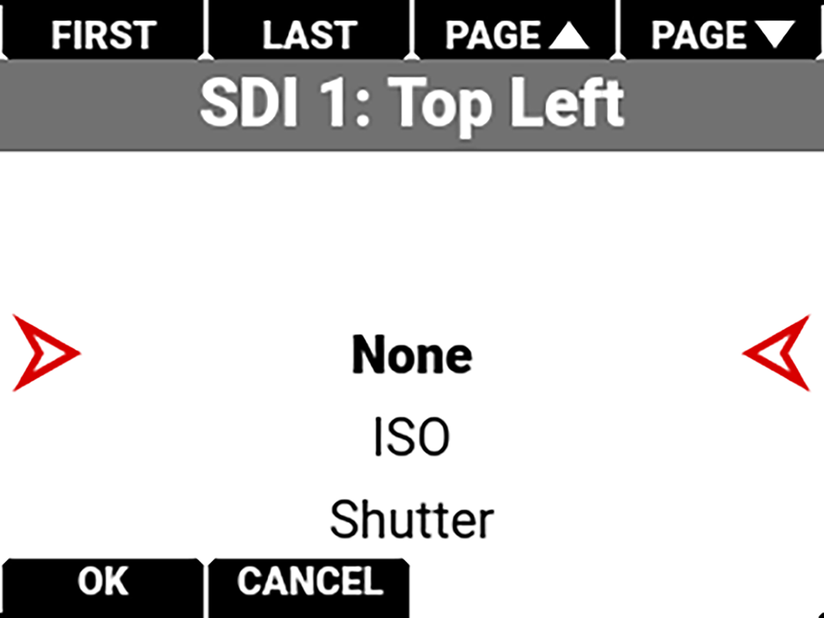
Use each of the location choices to select a value for the location.
The values you can display include:
|
Item |
Details |
|---|---|
|
None |
Nothing is assigned |
|
Horizon Level |
Displays the horizon orientation (center locations only) |
|
Horizon + Tilt Level |
Displays the horizon orientation plus added tilt (center locations only) |
|
Gyro Data |
Displays the gyro readings |
|
ISO |
Displays the ISO setting |
|
Shutter |
Displays the shutter setting |
|
Color Temperature |
Displays the color temperature |
|
Color Temperature and Tint |
Displays the color temperature and tint |
|
ND |
Displays the ND setting |
|
3D LUT |
Displays the 3D LUT |
|
Sensor Format |
Displays the sensor format |
|
Frame Rate |
Displays the frame rate |
|
Record Indicator |
Red indicator when recording |
|
Focal Length |
Displays the lens focal length |
|
Focus Distance |
Displays the lens focus distance |
|
Lens Information |
Displays the lens information |
|
Aperture |
Displays the aperture setting |
|
Camera Name |
Displays the camera name |
|
Clip Name |
Displays the clip name |
|
Slate Camera ID |
Displays the slate camera ID |
|
Slate Camera Position |
Displays the slate camera position |
|
Slate Camera Operator |
Displays the slate camera operator |
|
Slate Scene |
Displays the slate scene |
|
Slate Shot |
Displays the slate shot |
|
Slate Take |
Displays the slate take |
|
Slate Production |
Displays the slate production |
|
Slate Director |
Displays the slate director |
|
Slate DoP |
Displays the slate DoP |
|
Slate Unit |
Displays the slate unit |
|
Monitor Source |
Displays the source of the monitored image |
|
Media Time Remaining |
Displays the media time remaining |
|
Media Percentage Remaining |
Displays the percentage of media remaining |
|
Battery Time Remaining |
Displays the battery time remaining |
|
Battery Percentage Remaining |
Displays the battery percentage remaining |
|
Active Input Voltage |
Displays the active input voltage |
Overlay Opacity
Use Overlay Opacity to select the percentage of opacity you want the overlay to display on the SDI output.
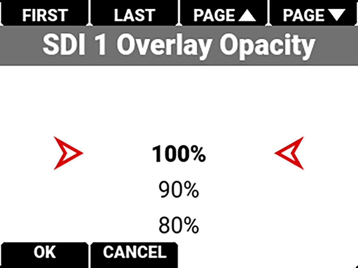
The settings you can select range from 100% (default) to 0%.
Magnify
Use Magnify to enable or disable the magnification of the output image. You can enable and disable magnification by pressing SEL to toggle Magnify to the right (green / enabled) and to the left (red / disabled).


Magnify Position (Global)
Use Magnify Position to select the area of the output image to magnify for all monitor outputs.
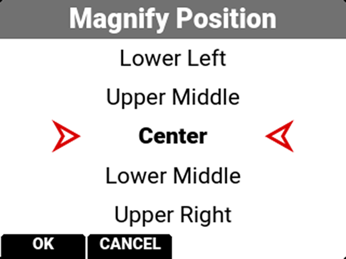
Use Magnify Position to globally select the area of the image you want to magnify.
The selections include:
|
• Left |
• Upper Middle |
• Upper Right |
|
• Upper Left |
• Center (default) |
• Lower Right |
|
• Lower Left |
• Lower Middle |
• Right |
Use Overlay Opacity to select the percentage of opacity you want the overlay to display on the SDI output.
The opacity values the camera can display are between 100% and 0%.
Flip / Mirror
Use Flip / Mirror to select the flip and mirror orientation you want to use for the EVF SDI port display.
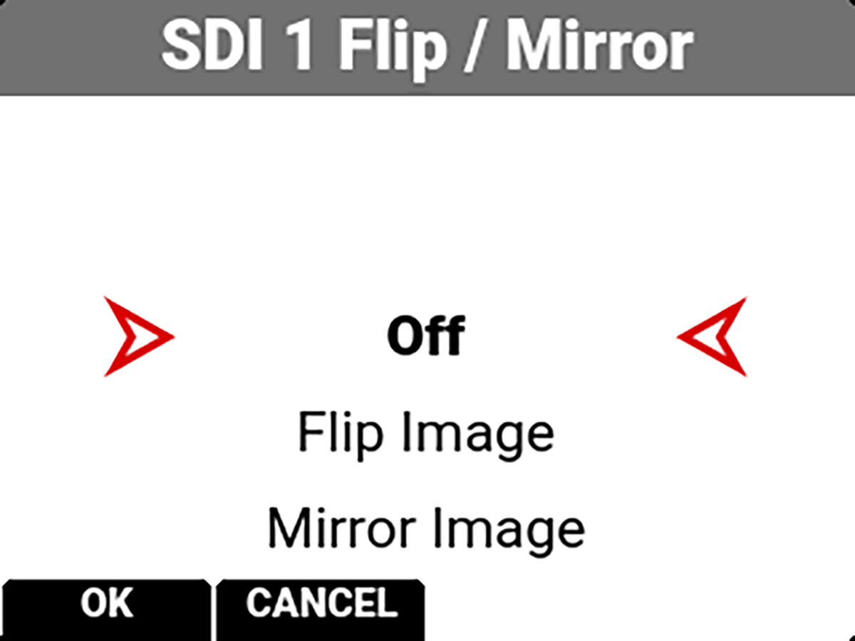
The Flip / Mirror settings you can select include:
• Off
• Flip Image
• Mirror Image
• Flip/Mirror Image
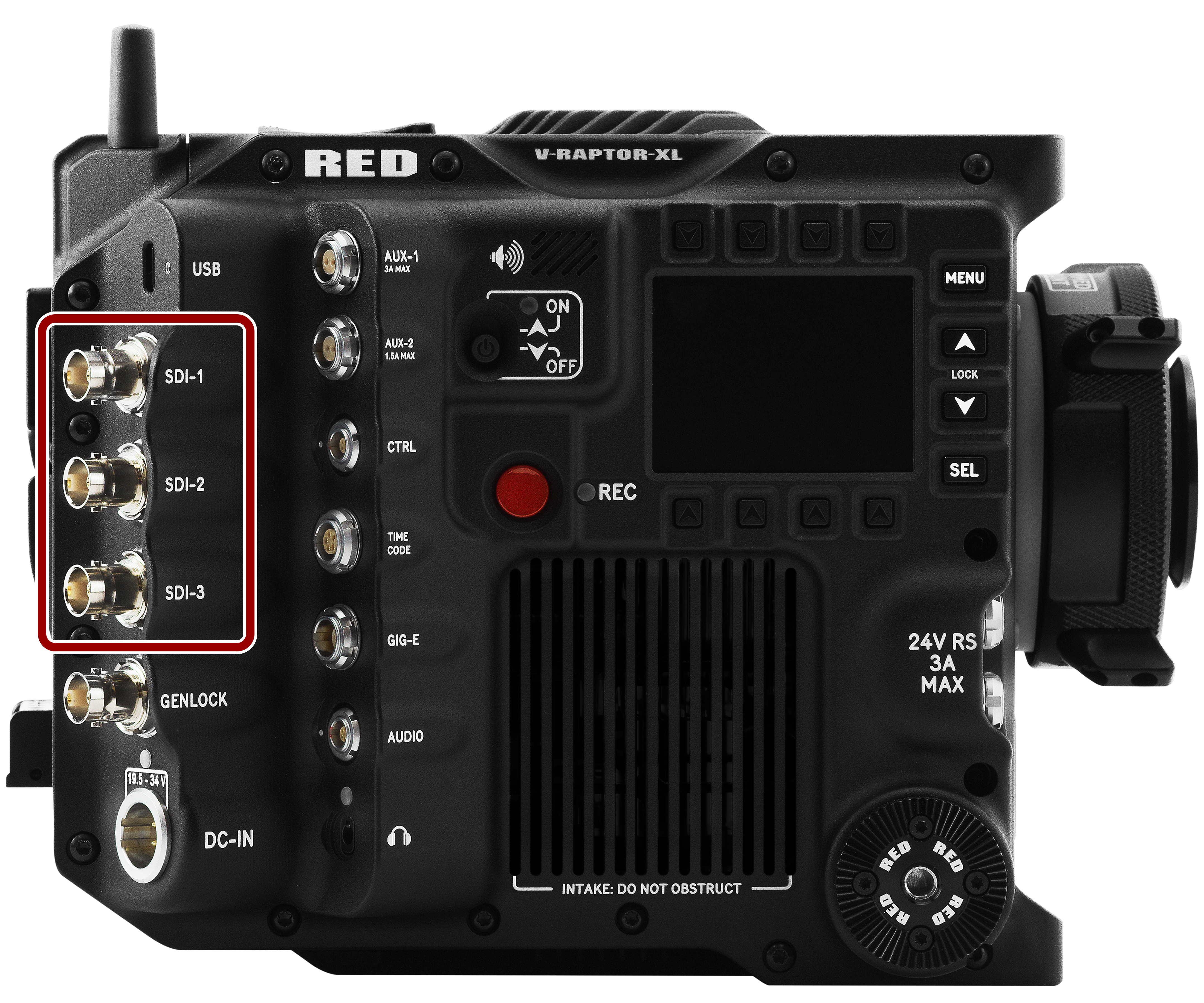
SDI Port Description
The Serial Digital Interface (SDI) ports allow the camera to deliver 12 Gbps of image bandwidth with greater resolution, frame rates, and color fidelity. These ports allow you to use a single BNC cable solution ideal for 4Kp60 format. The output signal bit depth is 10-bit 4:2:2.
|
|
|
For more information about SDI, refer to:
For more information about SDI safety, refer to Preventing Damage to SDI Outputs. |