RED® Cine-Broadcast Lens Control Cables
This section describes how to setup lens iris control with compatible lenses and a compatible RCP (Remote Control Panel).
Compatible RCP’s with both example configurations:
|
Brand |
SKU |
|---|---|
|
Cyanview |
CY-RCP |
|
Skarrhoj |
RCP-PRO-V2B-BK |
Setting up the cables
Configuration Example 1:
This configuration assumes that you are using the RED Cine-Broadcast Module and a compatible lens with a 12-pin Hirose connector.
This configuration enables iris control and the return command from focus or zoom demands attached to the lens. The return command from the demand triggers the Broadcast Module's Viewfinder to display the selected return feed.
Required Accessories
|
Item |
Description |
|---|---|
|
790-0804 |
RED® 12-Pin-to-Dual-12-Pin Lens Adapter Cable for RED® Cine-Broadcast Module |
|
790-0806 |
RED® 12-Pin-to-4-Pin Lens Communication Loopback Cable for RED® Cine-Broadcast Base Station |
|
790-0774 |
9.5" RED® 4-Pin-to-4-Pin CTRL (included in V-RAPTOR XL Cine-Broadcast Pack) |
|
790-0778 |
11" RED® 9-Pin-to-5-Pin Timecode, BNC, Genlock, and 4-Pin CTRL (included in V-RAPTOR Cine-Broadcast Pack) |
- Make sure that you fully configure the camera system and rig it while the RED Cine-Broadcast Module and lens are attached.
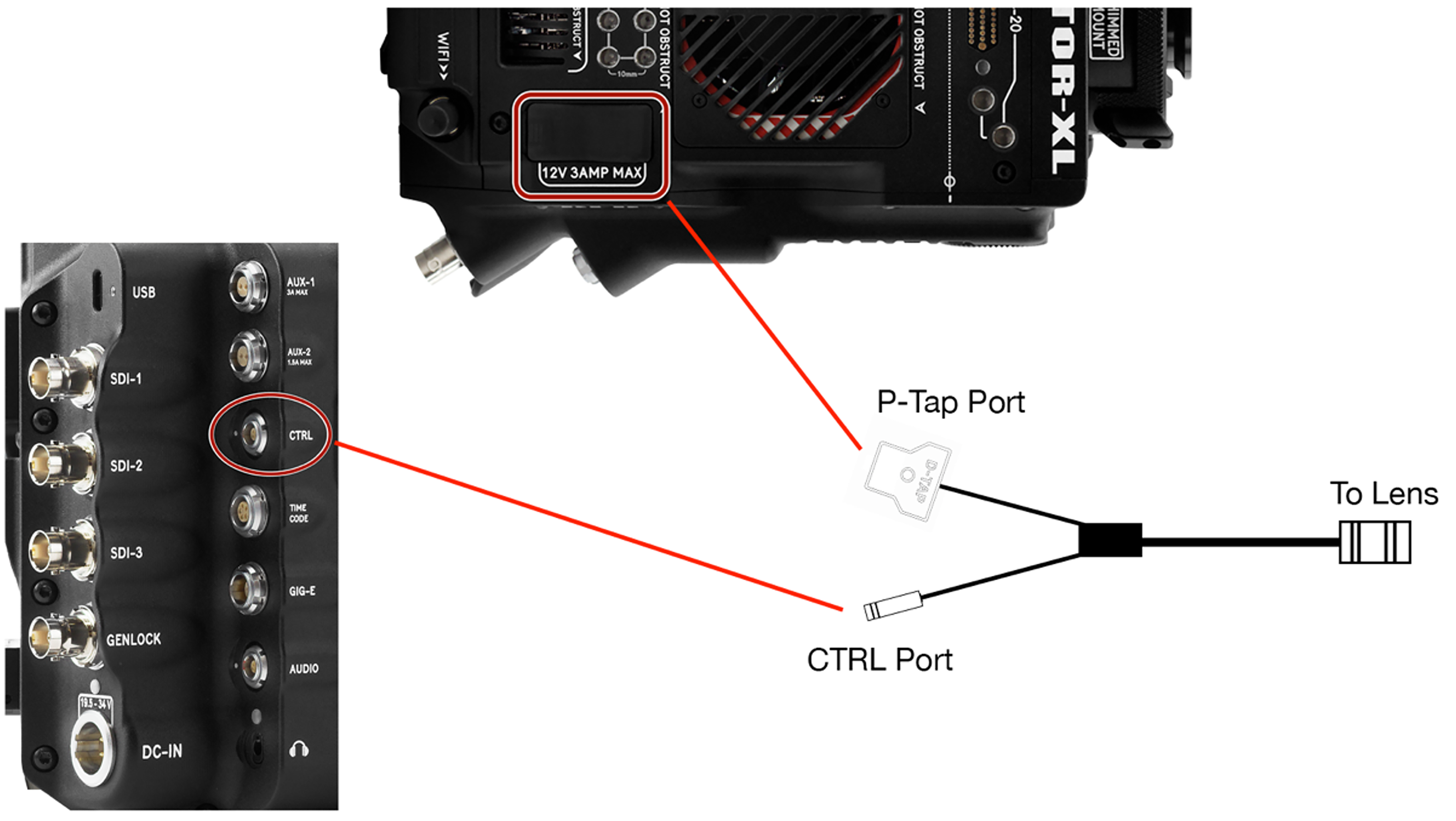
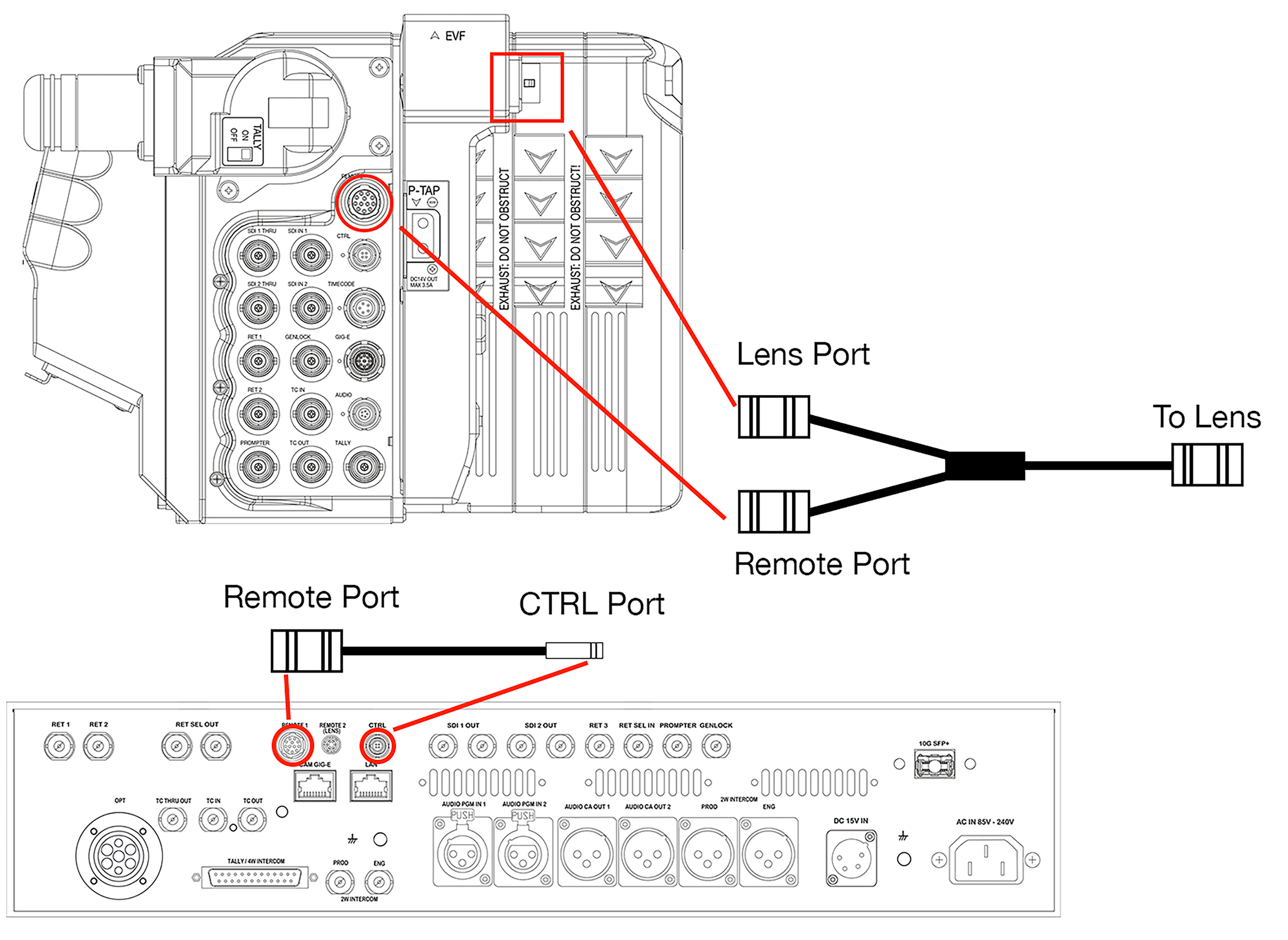
- For V-RAPTOR XL, connect the 4-Pin-to-4-Pin CTRL cable between the CTRL port on the RED Cine-Broadcast Module and the CTRL port on the V-RAPTOR XL. For V-RAPTOR, connect the 9-Pin-to-5-Pin Timecode, BNC, Genlock, and 4-Pin CTRL cable to the EXT port on the camera and the CTRL port on the RED Cine-Broadcast Module.
- Using the 12-Pin-to-Dual-12-Pin Lens adapter cable, connect the singled ended 12-Pin Hirose connector to the 12-Pin port on the lens.
- Connect the Dual 12-Pin connectors to the Lens and Remote ports on the RED Cine-Broadcast Module.
- Connect the RED® 12-Pin-to-4-Pin Lens Communication Loopback Cable's 12-Pin Hirose connector to the port marked Remote 1 on the RED Cine-Broadcast Base Station.
- Connect the 4-Pin CTRL Lemo connector to the CTRL port on the RED Cine-Broadcast Base Station.
Configuration Example 2:
This configuration assumes you want to control a compatible lens with a 12-Pin Hirose connector over IP with no RED Cine-Broadcast Module.
NOTE: This configuration will not trigger the return command from a lens demand if a RED Cine-Broadcast Module is attached.
Required Accessories
|
Item |
Description |
|---|---|
|
790-0814 |
RED® 12-Pin-to-4-Pin and PTap Broadcast Lens Control Cable |
|
Third-Party |
USB-C to Ethernet Adapter |
|
790-0655 |
9' RED GIG-E Right-to-CAT5E Ethernet Cable* |
|
720-0060 |
V-RAPTOR Expander Blade (not required for XL, XL has a dedicated CTRL port)** |
|
790-0759 |
V-RAPTOR Tactical Top Plate w/ Battery Adapter Plus |
* Optional for use with an XL configuration, where USB-C is not being used.
** V-RAPTOR Expander Blade not compatible with RED Cine-Broadcast Shoulder Mount.
- Make sure you fully configure the camera system, rig it with a USB-C to Ethernet Adapter or GIG-E to CAT5E cable and attach a lens.
- Connect the 12-Pin Hirose connector into the 12-Pin port on the lens.
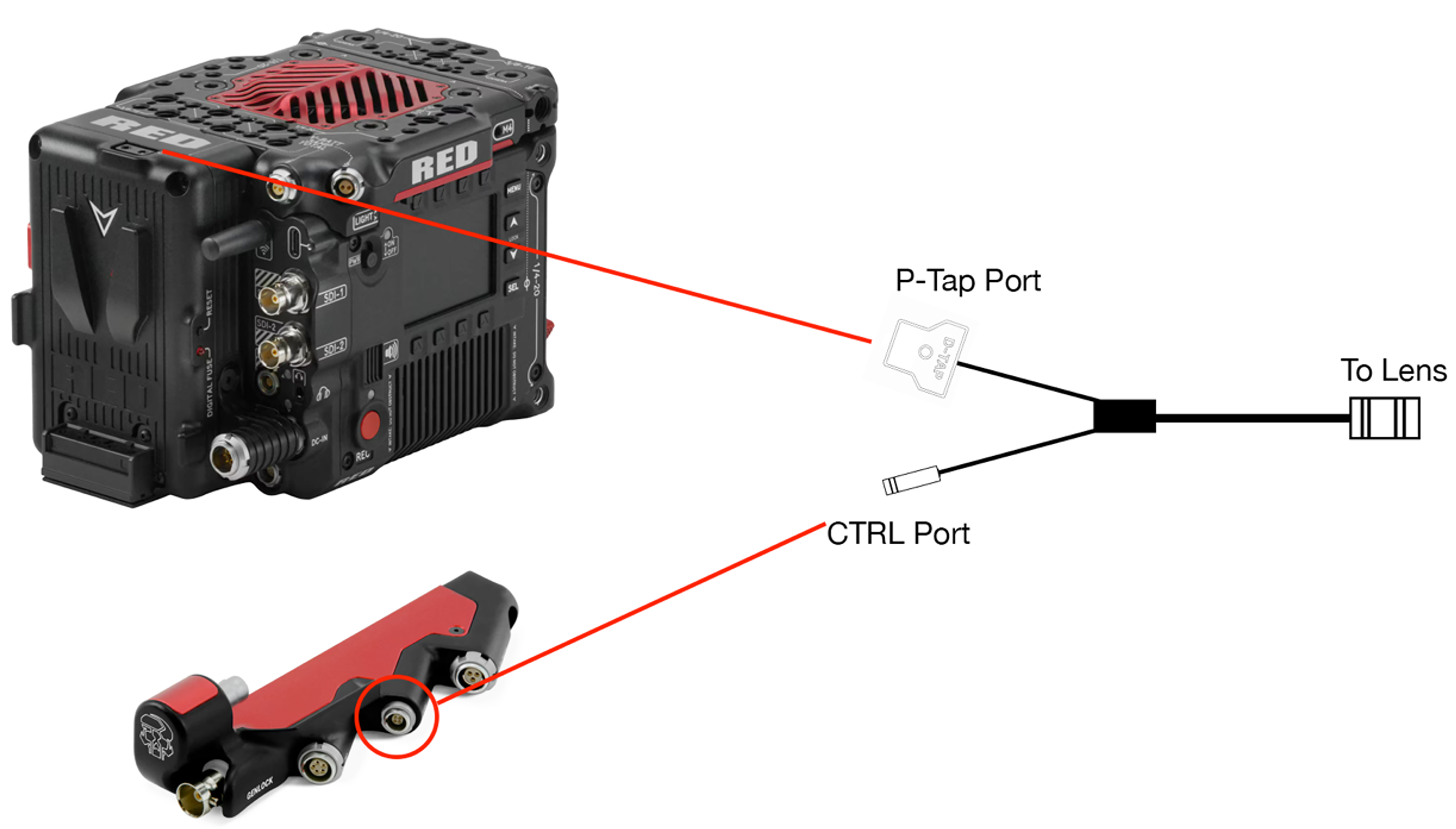
- Using the RED® 12-Pin-to-4-Pin and PTap Broadcast Lens Control Cable, connect the CTRL connector to the CTRL port on the V-RAPTOR XL, the V-RAPTOR Expander Blade, or a V-RAPTOR third-party 9-Pin breakout adapter. Connect the and D-TAP connector to the D-TAP port on the top of the V-RAPTOR XL or the V-RAPTOR Tactical Top Plate w/ Battery Adapter Plus.
- Connect an Ethernet cable to the USB-C to Ethernet adapter (V-RAPTOR) or a GIG-E to CAT5E cable (XL) to a network switch or directly to an RCP.