RED Cine-Broadcast Base Station (Half Rack)
This section describes the Front, and Back of the half rack space Base Station, and identifies the controls, buttons, and switches on the Base Station.
Front
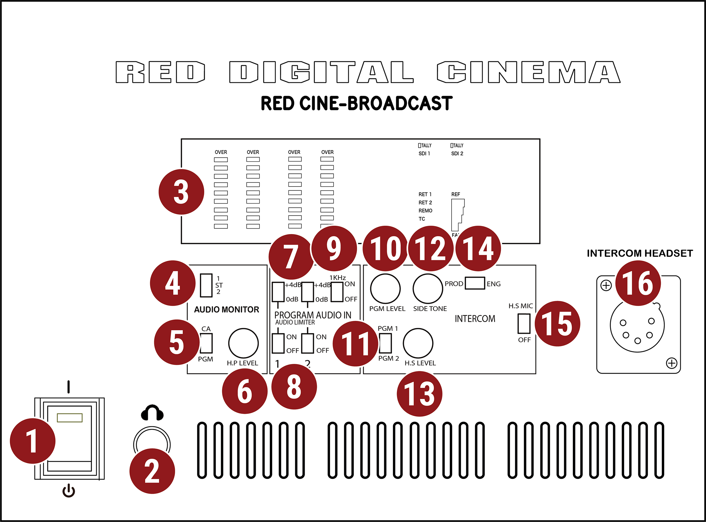
Figure: Half Rack Base Station Front, Controls and Features
|
# |
Item |
Description |
|---|---|---|
|
1 |
POWER |
Power on / off switch |
|
2 |
HEADPHONE |
6.35 mm stereo headphone port |
|
3 |
DISPLAY |
Signal status display screen |
|
4 |
AUDIO MONITOR |
Switch for selecting channel 1, stereo, or channel 2 |
|
5 |
CA / PGM |
Switch for monitoring camera audio (CA) or program audio (PGM) |
|
6 |
HP Level |
Headphone volume adjusting knob |
|
7 |
PGM AUDIO IN |
Program Audio In 0 dB or +4 dB boost switch for each channel |
|
8 |
PGM Limiter |
Program Audio In limiter switch for each channel |
|
9 |
PGM Test Signal |
Program Audio In 1 kHz test tone on / off switch |
|
10 |
PGM Level |
Intercom Program audio volume adjusting knob |
|
11 |
PGM Source |
Intercom Program audio PGM 1 / PGM 2 selection switch |
|
12 |
SIDE TONE |
Intercom side tone volume adjusting knob |
|
13 |
HS LEVEL |
Intercom headset volume adjusting knob |
|
14 |
PROD / ENG |
Intercom source switch to select Producer or Engineer |
|
15 |
HS MIC |
Intercom headset microphone on / off switch |
|
16 |
INTERCOM HS |
Intercom headset port, male XLR 5-Pin |
|
# |
Item |
Description |
|---|---|---|
|
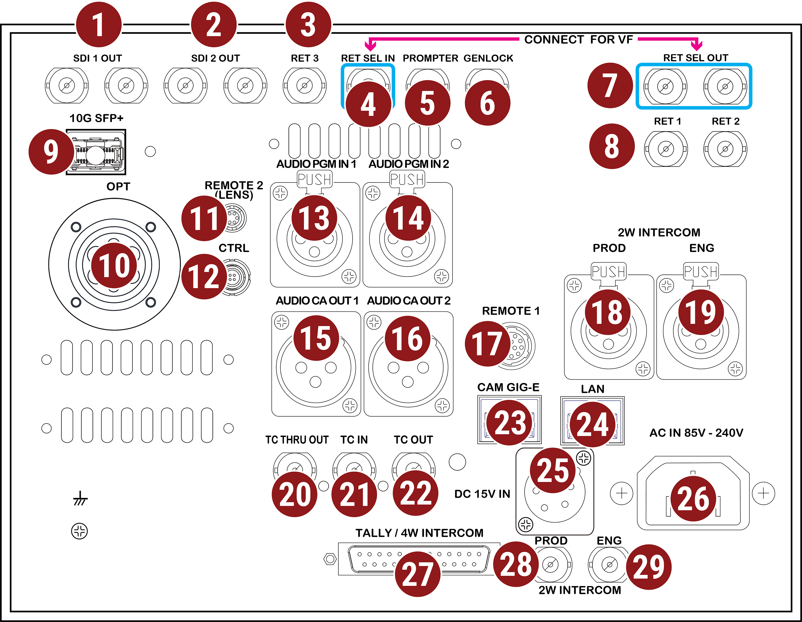
1 |
SDI OUT 1 |
BNC x 2, SDI output 1, 12G/6G/3G/1.5G-SDI |
|
2 |
SDI OUT 2 |
BNC x 2, SDI output 2, 12G/6G/3G/1.5G-SDI |
|
3 |
RET 3 |
BNC, SDI Return 3 input 12G/6G/3G/1.5G-SDI |
|
4 |
RET SEL IN |
BNC, SDI Return select input 1.5G-SDI viewfinder source |
|
5 |
PROMPTER |
BNC, teleprompter input 12G/6G/3G/1.5G-SDI |
|
6 |
GENLOCK |
BNC, Tri-level Genlock input |
|
7 |
RET SEL OUT |
BNC x 2, SDI Return select output |
|
8 |
RET 1 / 2 |
BNC x 2, SDI Return 1 and 2 input, 12G/6G/3G/1.5G-SDI1 (Viewable on VF) |
|
9 |
10G SFP+ |
SFP+ Cage (10Gbps) RED Connect input, Live 8K R3D or 4K JPEG-XS over SMPTE ST 21102 |
|
10 |
OPT |
LEMO, SMPTE 304M, camera connection |
|
11 |
REMOTE 2 |
6-Pin, Canon and Fujinon Lens and Iris Control |
|
12 |
CTRL |
LEMO 4-Pin x 1, Control protocol to camera |
|
13 |
AUDIO PGM 1 |
XLR 3-Pin, Program audio input 1, analog 2 channels, balanced, +4dBm |
|
14 |
AUDIO PGM 2 |
XLR 3-Pin, Program audio input 2, analog 2 channels, balanced, +4dBm |
|
15 |
AUDIO CA OUT 1 |
XLR 3-Pin, Camera audio output 1, analog 2 channels, balanced, +4dBm |
|
16 |
AUDIO CA OUT 2 |
XLR 3-Pin, Camera audio output 2, analog 2 channels, balanced, +4dBm |
|
17 |
REMOTE 1 |
12-Pin, RS-232/RS-422 auto detect |
|
18 |
PROD |
XLR 3-Pin, 2W Intercom input, Compatible with ClearCom and RTS |
|
19 |
ENG |
XLR 3-Pin, 2W Intercom input, Compatible with ClearCom and RTS |
|
20 |
TC THRU OUT |
BNC Timecode signal through output |
|
21 |
TC IN |
BNC, Timecode input SMPTE ST 12M |
|
22 |
TC OUT |
BNC, Timecode output SMPTE ST 12M |
|
23 |
CAM GIG-E |
RJ45, 1 Gbps for camera control3 |
|
24 |
LAN |
RJ45, 1 Gbps network trunk |
|
25 |
DC 15V IN |
XLR 4-Pin, 15 V DC input |
|
26 |
AC IN 85V - 240V |
IEC 60320, 85 V to 240 V AC input |
|
27 |
TALLY / 4W INTERCOM |
DB-25, Tally signal input, 4W Intercom input |
|
28 |
PROD |
BNC, 2W Intercom input, compatible with Protech (FD-400A) |
|
29 |
ENG |
BNC, 2W Intercom input, compatible with Protech (FD-400A) |
- Switching between the live preview and the return signal on the RED® Cine-Broadcast 7.0” Viewfinder requires the return signal to be 1.5G
- Requires a RED Connect license
- GIG-E and USB cannot be used simultaneously