RED® Cine-Broadcast Iris Cables
This section describes how to setup lens iris control with compatible lenses.
Setting up the Iris cables
This section contains the diagrams for connecting the iris control cable to the broadcast module, camera, and lens for V-RAPTOR and V-RAPTOR XL.
V-RAPTOR
V-RAPTOR Configuration Example
This configuration assumes that you are using the RED Cine-Broadcast Module and a compatible lens with a 12-pin Hirose connector.
This configuration enables iris control of the broadcast lens on V-RAPTOR.
Required Accessories
|
# |
Item |
Description |
|---|---|---|
|
1 |
790-0804 |
RED 12-Pin to dual 12-Pin lens adapter cable for RED Cine-Broadcast module ("lens y-cable") |
|
2 |
790-0821 |
RED 9-Pin to 5-Pin Timecode, BNC, Genlock, and 12-Pin lens communication for V-RAPTOR ("3-way cable") |
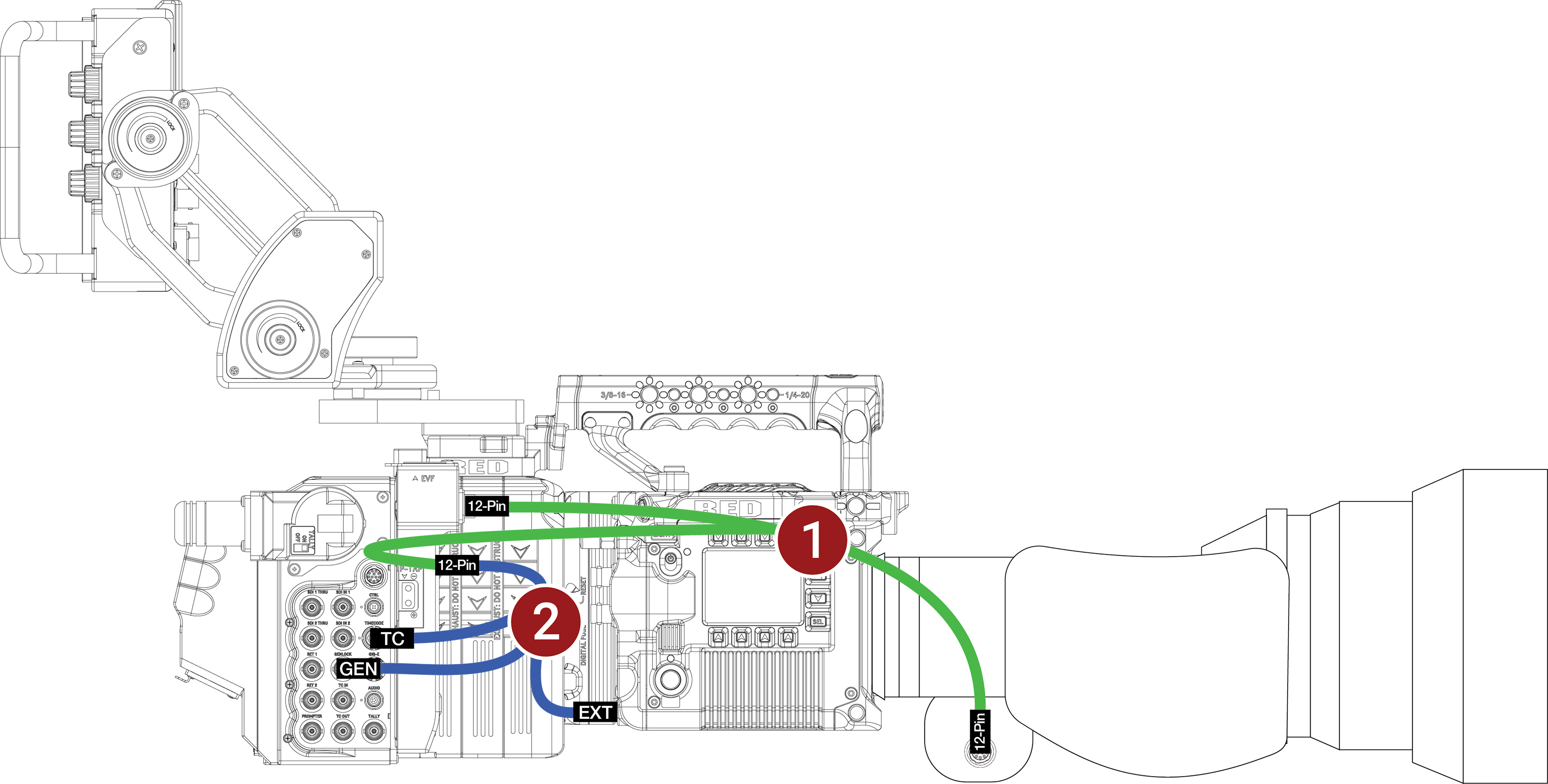
- Make sure that you fully configure the camera system and rig it while the RED Cine-Broadcast Module and lens are attached.
- Connect the RED 9-Pin to 5-Pin Timecode, BNC, Genlock, and 12-Pin lens communication for V-RAPTOR ("3-way cable") to the EXT port on the camera and to the RED 12-Pin to dual 12-Pin lens adapter cable for RED Cine-Broadcast module ("lens y-cable").
- Using the RED 12-Pin to dual 12-Pin lens adapter cable for RED Cine-Broadcast module ("lens y-cable"), connect the two remaining 12-Pin Hirose connectors to the lens port on the RED Cine-Broadcast Module, and attach the other 12-Pin connector to the port on the broadcast lens.
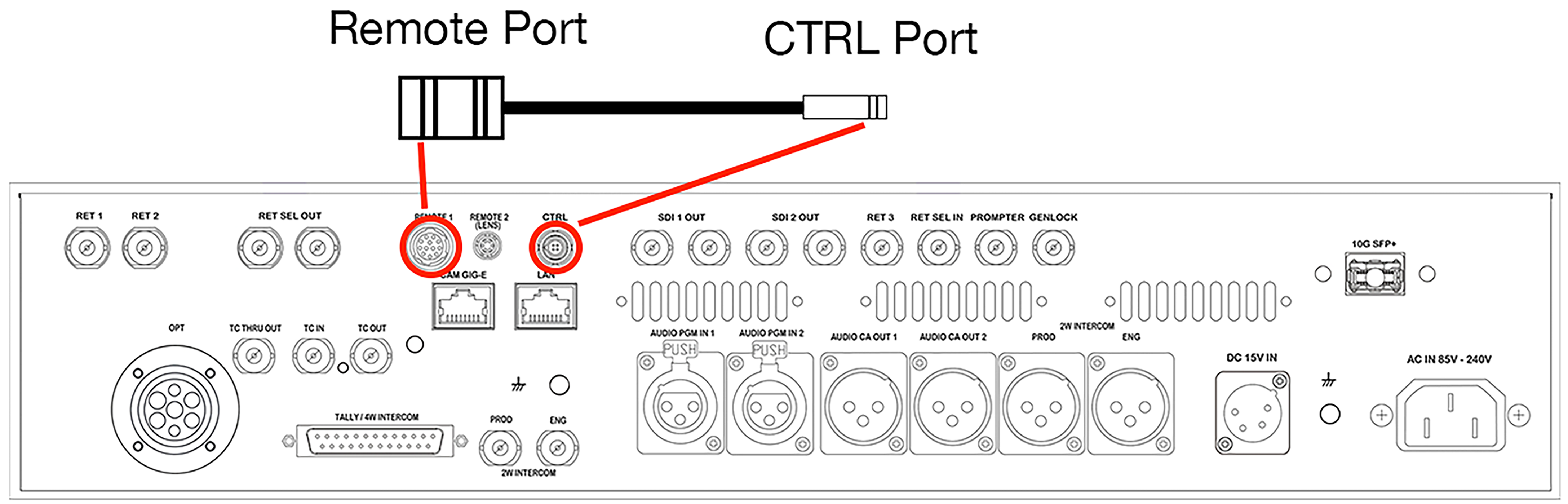
NOTE: Remove the Remote Port to CTRL Port cable from the back of the RED Cine-Broadcast Base Station.
V-RAPTOR XL
V-RAPTOR Configuration Example
This configuration assumes that you are using the RED Cine-Broadcast Module and a compatible lens with a 12-pin Hirose connector.
This configuration enables iris control of the broadcast lens on V-RAPTOR.
Required Accessories
|
# |
Item |
Description |
|---|---|---|
|
1 |
790-0804 |
RED 12-Pin to dual 12-Pin lens adapter cable for RED Cine-Broadcast module ("lens y-cable") |
|
2 |
790-XXXX |
12-Pin to 4-Pin 00B CTRL (RCP2 communication) |
|
3 |
790-XXXX |
Timecode 5-Pin 0B to 5-Pin 0B |
|
4 |
790-XXXX |
Genlock BNC to BNC |
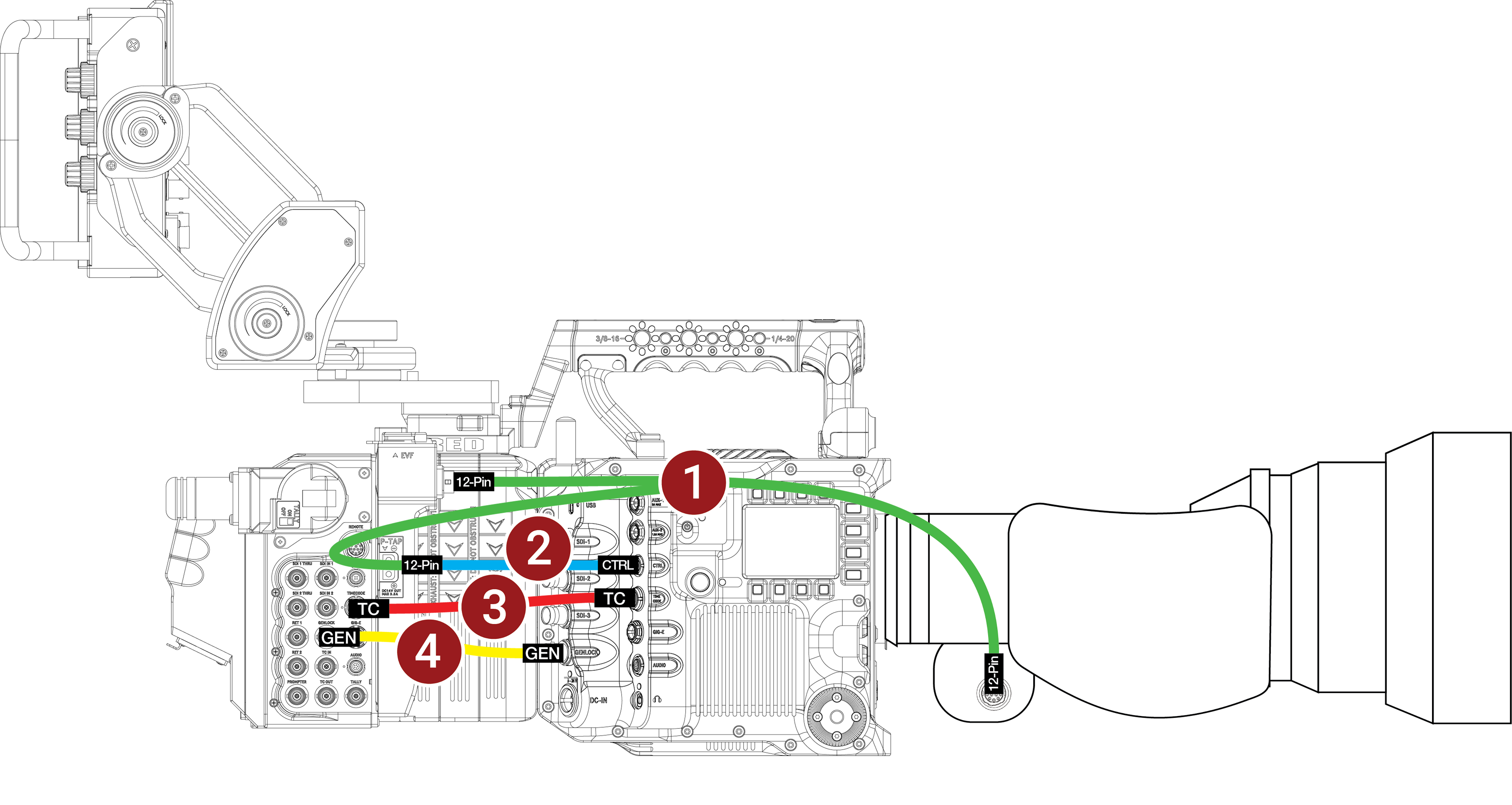
- Make sure that you fully configure the camera system and rig it while the RED Cine-Broadcast Module and lens are attached.
- Connect the Genlock BNC cable to the RED Cine-Broadcast Module Genlock port and to the V-RAPTOR XL Genlock port.
- Connect the Timecode 5-Pin cable to the RED Cine-Broadcast Module Timecode port and to the V-RAPTOR XL Timecode port.
- Connect the 12-Pin to 4-Pin 00B CTRL (RCP2 communication) cable to the V-RAPTOR XL 4-Pin CTRL port.
- Using the RED 12-Pin to dual 12-Pin lens adapter cable for RED Cine-Broadcast module ("lens y-cable"), connect the 12-Pin Hirose connectors to the lens port on the RED Cine-Broadcast Module, to the 12-Pin lens port on the broadcast lens, and to the 12-Pin end of the 12-Pin to 4-Pin 00B CTRL (RCP2 communication) cable.
NOTE: Remove the Remote Port to CTRL Port cable from the back of the RED Cine-Broadcast Base Station.