Camera Body
This section describes the Front, Top, Left, Right, Back: V-Lock, Back: Gold Mount, and Bottom of the camera, and identifies the controls, buttons, Camera Body LEDs, and the lens mount on the body.
Front
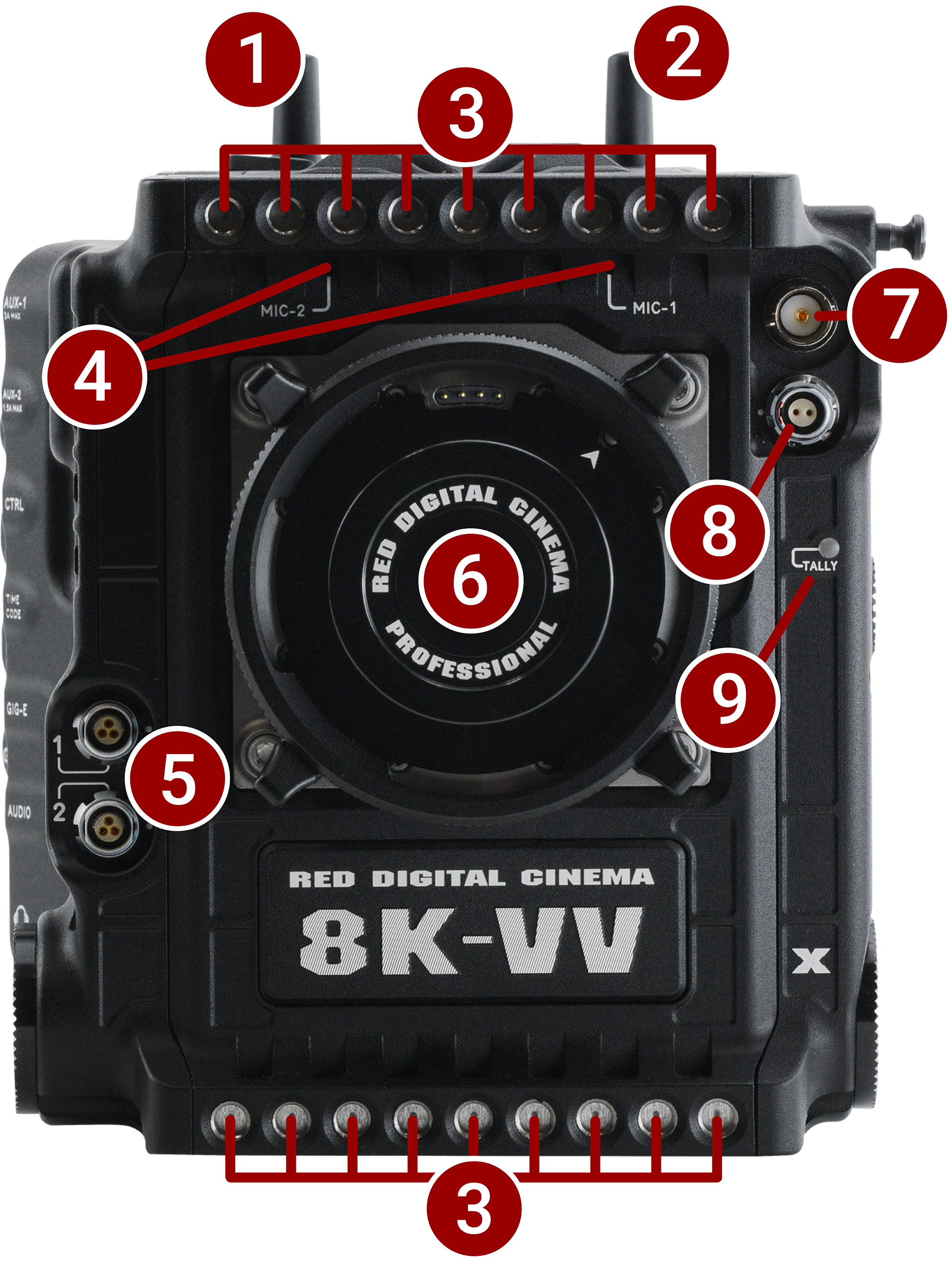
Figure: Camera Body Front, Controls and Features
|
# |
Item |
Description |
|---|---|---|
|
1 |
Wi-Fi Antenna |
Wi-Fi antenna mounted to a female RP-SMA connector. Supports 2.4 GHz and 5 GHz |
|
2 |
ACN Antenna |
Receiver for wireless Genlock and Timecode over Ambient Communication Network |
|
3 |
Mounting holes |
18 x ¼-20 mounting holes |
|
4 |
Microphones |
Internal Microphones 1 and 2 |
|
5 |
24 V RS |
Two 3-Pin Fischer 24 volt, 3 amp power output R/S ports |
|
6 |
Lens mount |
Interchangeable mount, shimmable locking PL, or locking EF |
|
7 |
EVF port |
3G-SDI BNC port with output mirrored from the rear BNC port |
|
8 |
AUX power |
2-Pin regulated 12 volt, 1 amp power for EVF |
|
9 |
Tally Light |
LED that indicates when the camera is recording |
|
# |
Item |
Description |
|---|---|---|
|
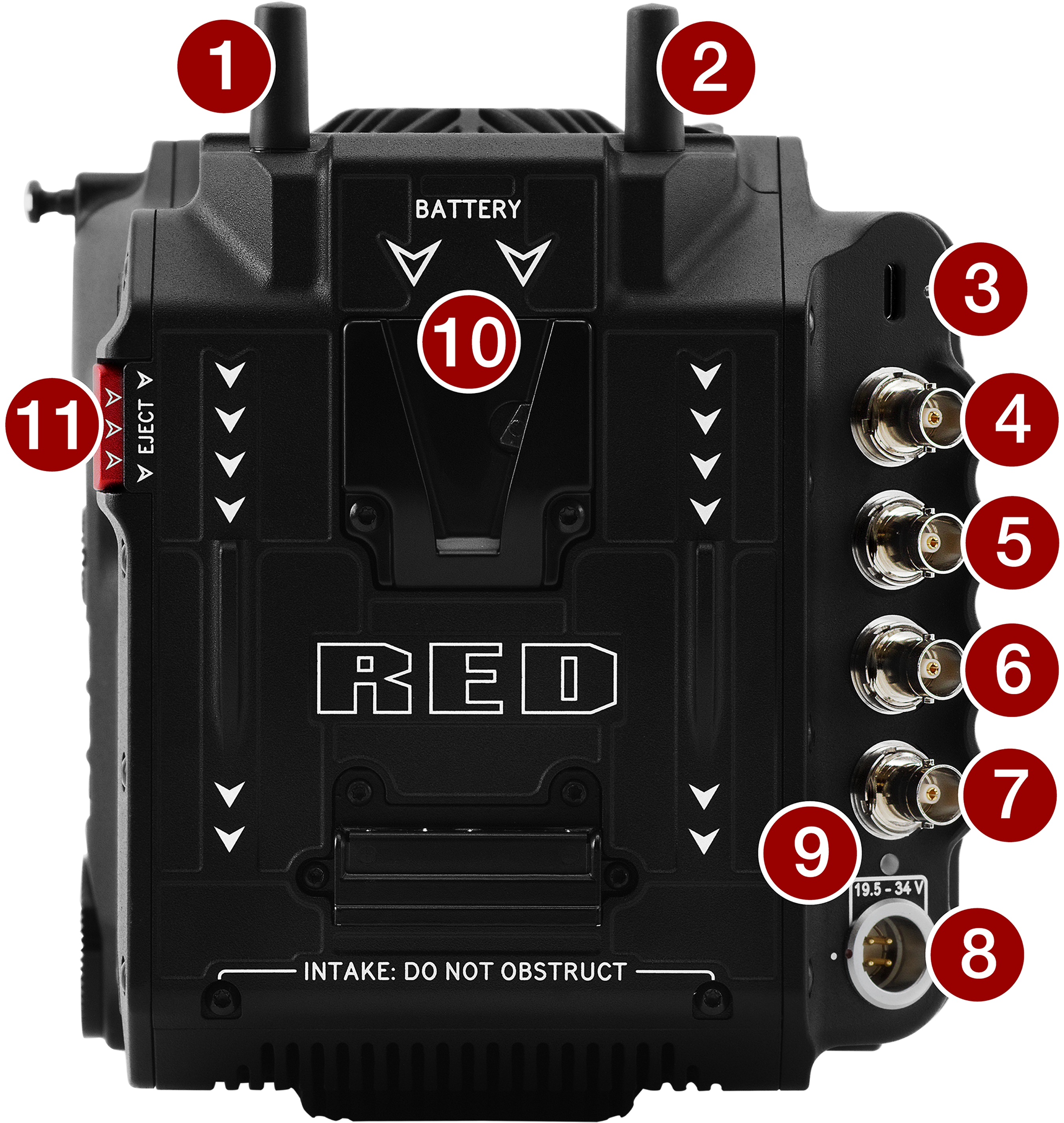
1 |
ACN Antenna |
Receiver for wireless Genlock and Timecode over Ambient Communication Network |
|
2 |
Wi-Fi Antenna |
A Wi-Fi antenna mounted to a female RP-SMA connector (supports 2.4 GHz and 5 GHz) |
|
3 |
USB-C port |
Supports remote camera control, R3D streaming using RED Connect License (with 5 Gb/s Ethernet adapter), and 5 watt USB charging |
|
4, 5, 6 |
12G-SDI 1 / 2 / 3 ports1,2 |
Full-size 12G-SDI BNC port for SDI monitor connection |
|
7 |
Genlock |
Genlock 75 Ohm BNC |
|
8 |
DC-IN port |
4-Pin 2L for DC-IN (19.5 to 34 volts) |
|
9 |
DC power LED |
Indicates state of DC power (refer to Camera Body LEDs) |
|
10 |
Battery mount |
V-Lock version (supports 14 and 26 volts) |
|
11 |
Eject |
Battery eject button |
- Use certified 12G-SDI cables.
- WARNING: Always connect the accessories' DC power cable (or batteries) before connecting the BNC SDI cable. Always remove the BNC SDI cable before removing the accessories' DC power cable (or batteries). Refer to SDI 1 / 2 / 3.
|
# |
Item |
Description |
|---|---|---|
|
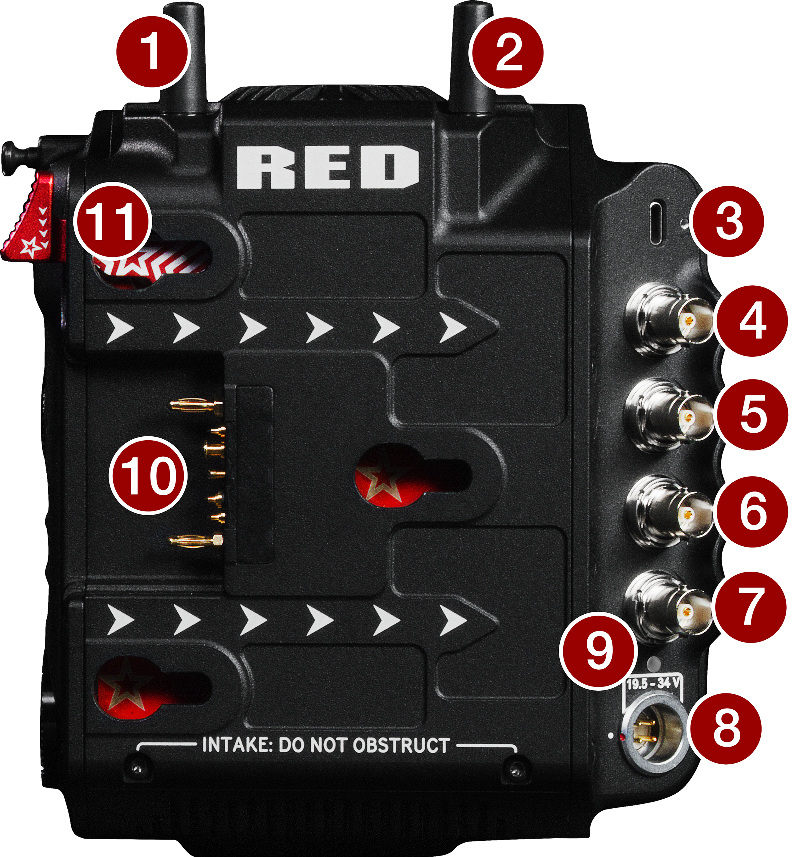
1 |
ACN Antenna |
Receiver for wireless Genlock and Timecode over Ambient Communication Network |
|
2 |
Wi-Fi Antenna |
A Wi-Fi antenna mounted to a female RP-SMA connector (supports 2.4 GHz and 5 GHz) |
|
3 |
USB-C port |
Supports remote camera control, R3D streaming using RED Connect License (with 5 Gb/s Ethernet adapter), and 5 W USB charging |
|
4, 5, 6 |
12G-SDI 1 / 2 / 3 ports1,2 |
Full-size 12G-SDI BNC port for SDI monitor connection |
|
7 |
Genlock |
Genlock 75 Ohm BNC |
|
8 |
DC-IN port |
4-Pin 2L for DC-IN (19.5 to 34 volts) |
|
9 |
DC power LED |
Indicates state of DC power (refer to Camera Body LEDs) |
|
10 |
Battery mount |
Gold Mount version (supports 14 and 26 volts) |
|
11 |
Eject button |
Gold Mount battery eject button |
- Use certified 12G-SDI cables.
- WARNING: Always connect the accessories' DC power cable (or batteries) before connecting the BNC SDI cable. Always remove the BNC SDI cable before removing the accessories' DC power cable (or batteries). Refer to SDI 1 / 2 / 3.
Left
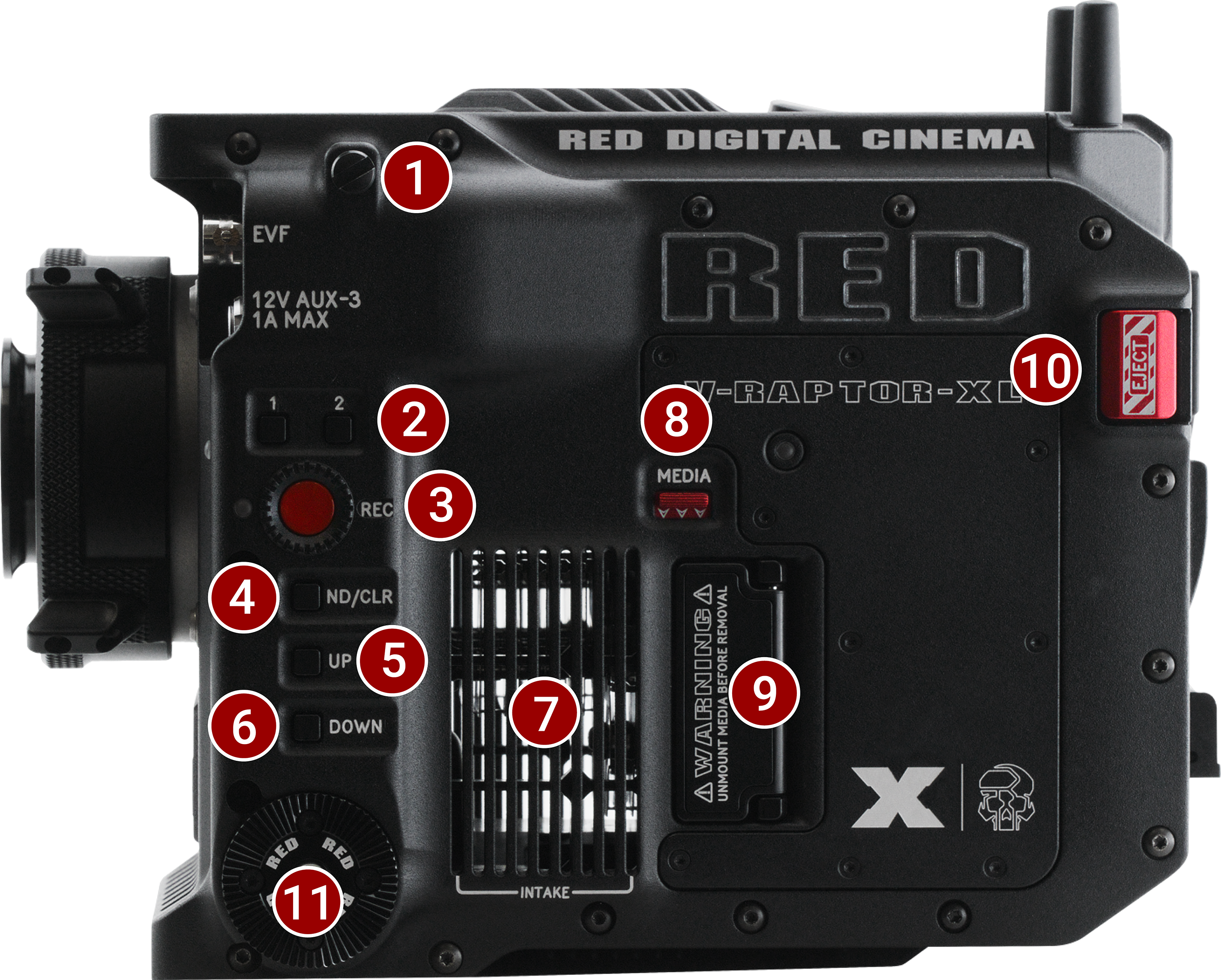
Figure: Camera Body Left, Controls and Features
|
# |
Item |
Description |
|---|---|---|
|
1 |
Focus screw |
Focus plane screw |
|
2 |
User Buttons |
Assignable user buttons |
|
3 |
REC |
Record button |
|
4 |
ND/CLR |
Toggles between clear and last used ND filter setting |
|
5 |
UP |
Increases ND |
|
6 |
DOWN |
Decreases ND |
|
7 |
Intake |
Cooling fan air intake |
|
8 |
Media |
Latch for CFexpress Type B media compartment door |
|
9 |
Media compartment |
Covered CFexpress Type B compartment |
|
10 |
Battery eject |
Eject button for battery |
|
11 |
Rosette |
M6 60-tooth rosette for mounting RED® Production Grips |
Right
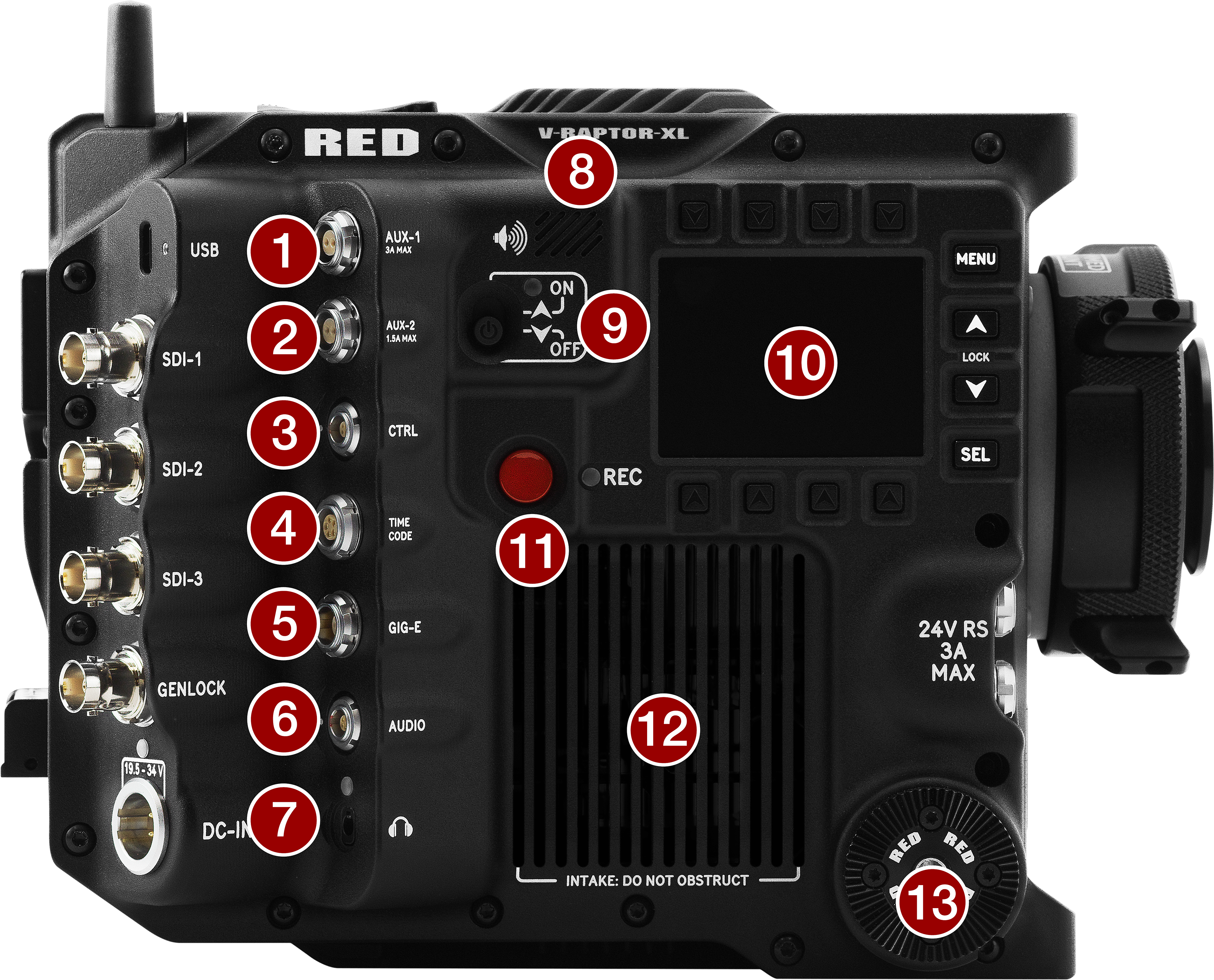
Figure: Camera Body Right, Controls and Features
|
# |
Item |
Description |
|---|---|---|
|
1 |
AUX-1 |
2-Pin 0B 12 volt, 3 amp output |
|
2 |
AUX-2 |
2-Pin 0B 12 volt, 1.5 amp output |
|
3 |
CTRL |
4-Pin 00B for RPC2 communication |
|
4 |
TIMECODE |
5-Pin 0B for Timecode |
|
5 |
GIG-E |
9-Pin 0B 1000BASE-T (IEEE 802.3ab) Gigabit Ethernet |
|
6 |
AUDIO |
5-Pin 00B for 2 audio Line, Mic, and +48 volts |
|
7 |
Headphone |
3.5 mm stereo headphone port |
|
8 |
Speaker |
Beep speaker |
|
9 |
Power switch |
Turns the power on and off |
|
10 |
Side LCD |
Side LCD displays UI screens include UI navigation buttons |
|
11 |
REC |
Record button and LED indicator |
|
12 |
Intake |
Cooling fan air intake |
|
13 |
Rosette |
M6 60-tooth rosette for mounting RED® Production Grips |
Top

Figure: Camera Body Top, Controls and Features
|
# |
Item |
Description |
|---|---|---|
|
1 |
ACN antenna |
Receiver for wireless Genlock and Timecode over Ambient Communication Network |
|
2 |
Wi-Fi antenna |
A Wi-Fi antenna mounted to a female RP-SMA connector (supports 2.4 GHz and 5 GHz) |
|
3 |
I/O Exhaust |
Cooling fan hot I/O exhaust |
|
4 |
Mounting holes |
12 top ¼-20 mounting holes |
|
5 |
Main Exhaust |
Main cooling fan hot exhaust |
|
6 |
Accessory port |
Connection port for accessories (refer to DSMC3™ RED® Touch 7.0" LCD) |
|
7 |
Focus screw |
Focus plane screw |
|
8 |
P-Tap |
Two 12 volt 3 amp shared P-Tap outputs |
|
9 |
Focus plane |
Focus plane line |
|
10 |
Mounting holes |
4 front top ¼-20 mounting holes |
Bottom
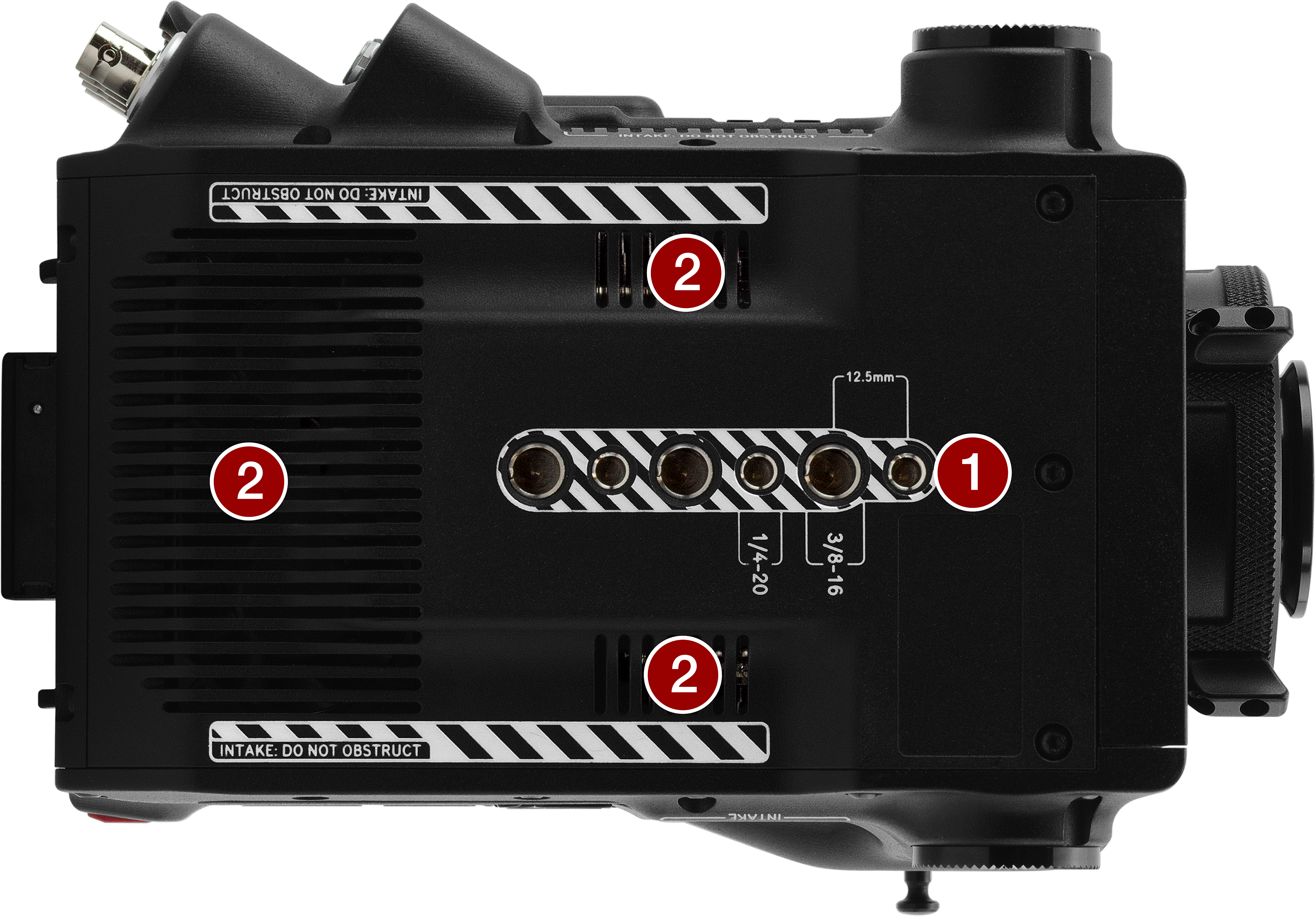
Figure: Camera Body Bottom, Controls and Features
|
# |
Item |
Description |
|---|---|---|
|
1 |
Mounting points |
3 x 1/4"-20 mounting holes and 3 x 3/8"-16 mounting holes |
|
2 |
Air intakes |
Cooling fan air intake |
Camera Body LEDs
Front LED
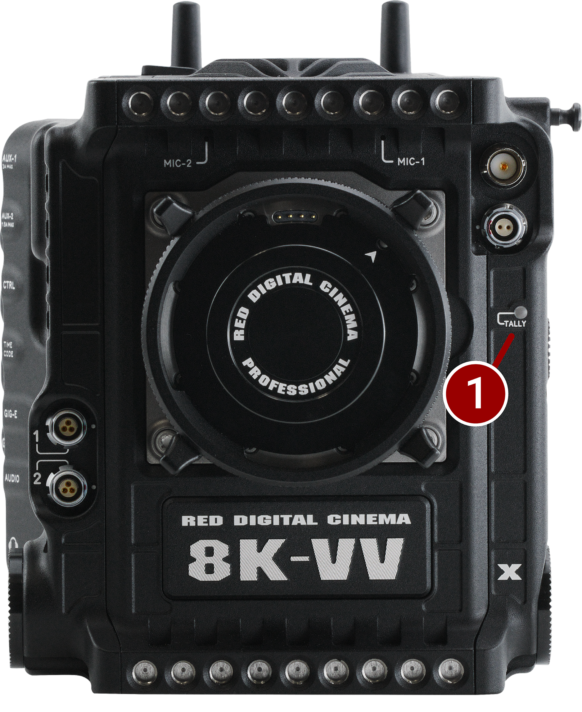
Figure: Camera Body Front LED
|
# |
Item |
Color |
Description |
|---|---|---|---|
|
1 |
Tally Indicator LED |
Red |
When enabled, this LED is ON when the camera is recording. For information about enabling this LED, refer to Indicators |
Back LED
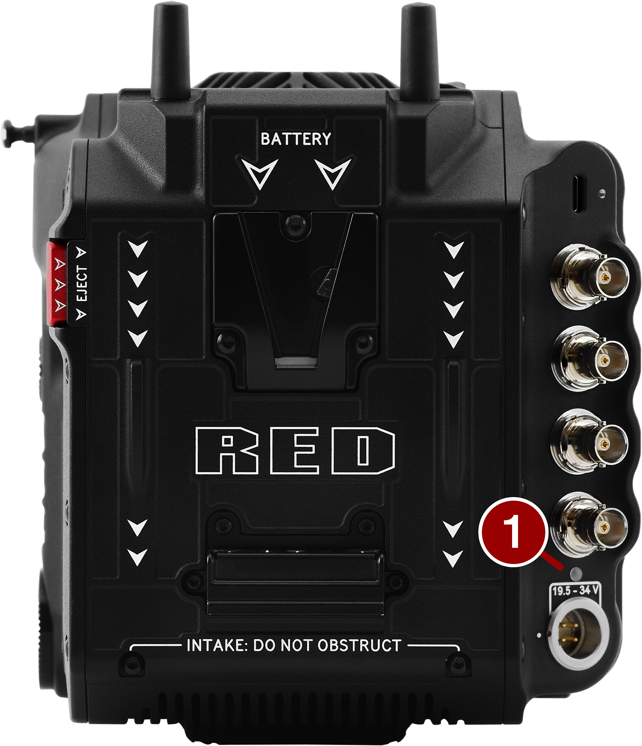
Figure: Camera Body Back LED
|
# |
Item |
Color |
Description |
|---|---|---|---|
|
1
|
DC-IN
|
Off |
No power detected. Check polarity and source voltage level |
|
Green |
DC-IN is present, and it is supplying between 19.5 and 34 volts |
Left Side LEDs
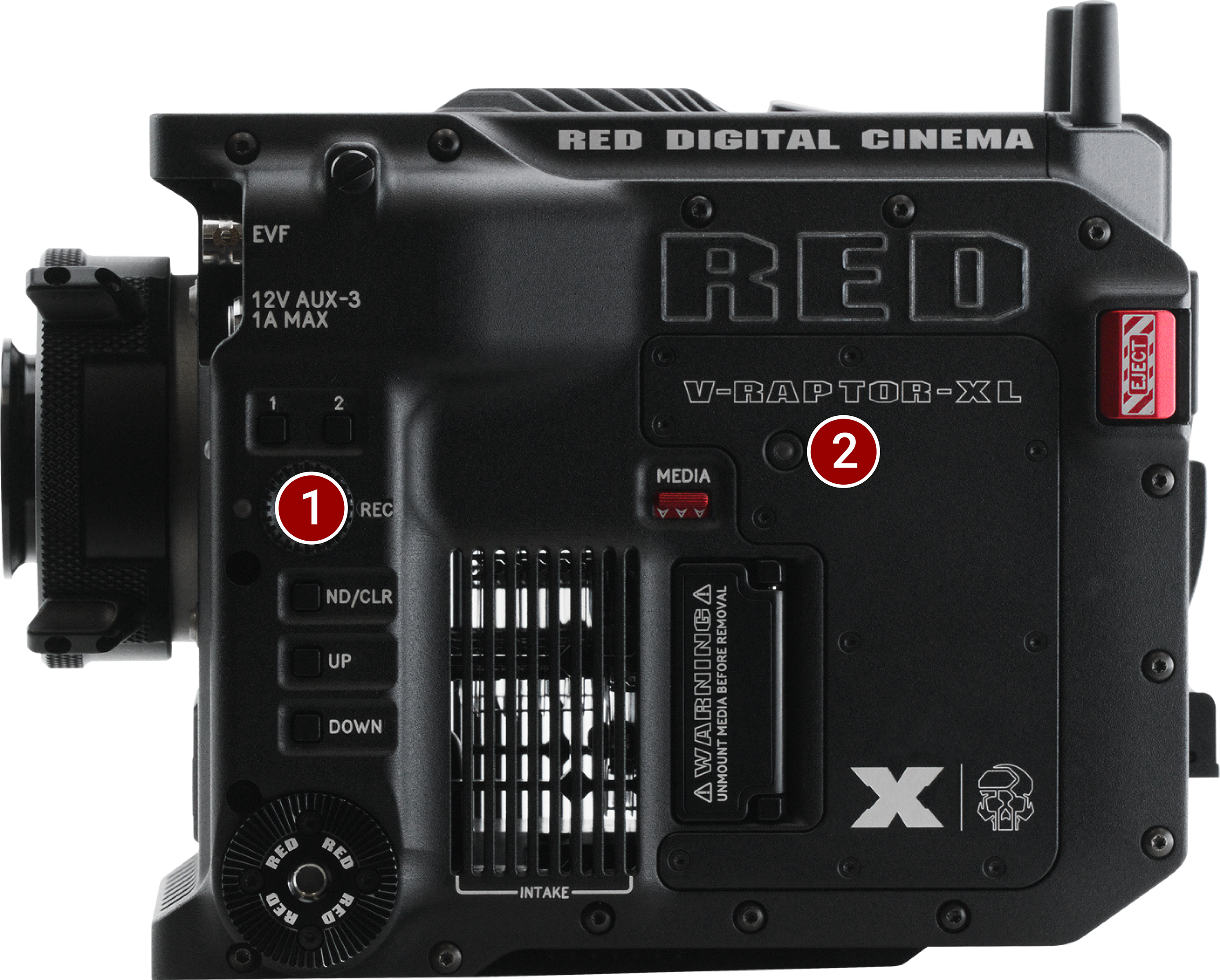
Figure: Camera Body Left Side LEDs
|
# |
Item |
Color/Flashing |
Description |
|---|---|---|---|
|
1
|
Record status (REC) |
Off |
No media present |
|
Green |
Ready to record |
||
|
Red |
Recording |
||
|
Amber |
Finalizing |
||
|
Red flashing slow |
Media mounted with >5% and <= 10% of media space available |
||
|
Red flashing fast |
Media mounted with <= 5% of media space available |
||
|
2 |
CFexpress Media LED |
Off |
No media mounted |
|
Green |
Preview; media mounted with > 10% of media space available |
||
|
Amber |
Recording finalizing or playback mode |
||
|
Amber flashing slow |
Formatting media |
||
|
Red flashing slow |
Media mounted with >5% and <= 10% of media space available |
||
|
Red flashing fast |
Media mounted with <= 5% of media space available |
||
|
Red |
Recording with > 10% of media space available |
Right Side LEDs
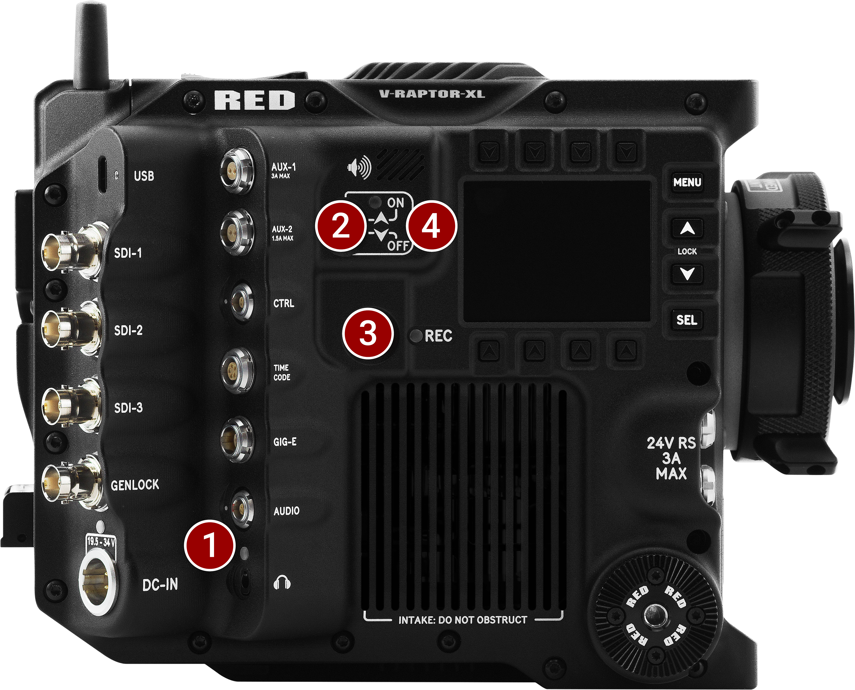
Figure: Camera Body Right Side LEDs
|
# |
Item |
color/flashing |
Description |
|---|---|---|---|
|
1 |
Audio |
Blue |
+48 volt Phantom power |
|
2 |
Power (ON) |
Off |
Camera off |
|
Green |
Camera on |
||
|
Green |
Camera on |
||
|
Amber flashing |
Camera on; 5 to 10 min of battery time available |
||
|
Red flashing |
Camera on; < 5 min of battery time available |
||
|
Red |
Camera shutting down |
||
|
3
|
Record status (REC) |
Off |
No media present |
|
Green |
Ready to record |
||
|
Red |
Recording |
||
|
Amber |
Finalizing |
||
|
Red flashing slow |
Media mounted with >5% and <= 10% of media space available |
||
|
Red flashing fast |
Media mounted with <= 5% of media space available |
||
|
4 |
Power (firmware update) |
Flashing green |
Firmware update in progress |
|
Flashing red |
Firmware update error (refer to Upgrading the Firmware) |