RED RANGER GEMINI Camera Body
This section describes the controls, buttons, and features on the RED RANGER GEMINI camera body. For information on the input/output connectors, go to Input/Output Connectors.

Figure: Camera Body Controls and Features
Camera Body Controls and Features
Camera Front

Figure: Camera Body Controls and Features
|
# |
Item |
Description |
|---|---|---|
|
1 |
Lens mount area |
Attach lens mount |
|
2 |
Mic 1 |
Left audio channels: Ch1 and Ch3. Go to Audio System |
|
3 |
Mic 2 |
Right audio channels: Ch2 and Ch4. Go to Audio System |
|
4 |
User Key 2 |
Programmable key User Key 1 + 2 Press: Eject Media |
|
5 |
REC Button |
Programmable key Full Press: Record Toggle Half Press: AF Start |
|
6 |
User Key 1 |
Programmable key User Key 1 + 2 Press: Eject Media |
Camera Top

Figure: Camera Body Controls and Features
|
# |
Item |
Description |
|---|---|---|
|
7 |
Primary EVF/LCD Port |
Mount a DSMC2 RED Touch LCD, LCD/EVF Adaptor A, or LCD/EVF Adaptor D |
|
8 |
Top Handle Port |
Mount the DSMC2 Top Handle or DSMC2 Outrigger Handle. This is the only mounting option for the DSMC2 Top Handle or DSMC2 Outrigger Handle (it cannot be attached backward) |
|
9 |
Fan intake |
DO NOT block fan intake when the camera is on |
Camera Left

Figure: Camera Body Controls and Features
|
# |
Item |
Description |
|---|---|---|
|
10 |
PWR/REC button |
Fully press and hold the PWR/REC key for two (2) seconds to turn on/off. When the camera is on, fully press and then release the PWR/REC key to toggle record start/stop. |
|
11 |
Industry-standard rosette |
Features an M6 threaded hole in the center; use with cages or accessories that feature rosette-based mounting systems |
|
12 |
Focal plane marks |
Marks align with the sensor plane; pull focus from these marks. |
|
13 |
Side LCD and Navigation |
Go to Side LCD and Navigation |
|
14 |
Wireless (802.11g) antenna |
Uses standard female SMA connector; can be replaced with taller SMA connector antennas |
Camera Right

Figure: Camera Body Controls and Features
|
# |
Item |
Description |
|---|---|---|
|
15 |
Focus Hook Screw Storage Location1 |
Store the focus hook screw |
|
16 |
Focal plane marks |
Marks align with the sensor plane; pull focus from these marks. |
|
17 |
Focus Hook Mounting Point1 |
Mount the focus hook |
|
18 |
Secondary EVF/LCD Port |
Mount a DSMC2 RED Touch LCD or LCD/EVF Adaptor D. The secondary LCD/EVF port and a MON-1 port cannot be used at the same time. Go to Monitor Preferences |
|
19 |
Hook and loop patch |
Rectangle of hook and loop material for attaching labels |
- Install only the focus hook screw to this mounting point. Damage to the media bay or other components of the camera system caused by installing other devices is not covered under warranty.
Camera Back

Figure: Camera Body Controls and Features (shown with gold mount)
|
# |
Item |
Description |
|---|---|---|
|
20 |
Battery mount |
Depending on the RED RANGER type, you can attach either a gold mount battery or a v-lock battery |
|
21 |
Media mount |
Mount RED MINI-MAG media |
|
22 |
Fan exhaust |
DO NOT block fan exhaust when the camera is on |
Camera Bottom

Figure: Camera Body Controls and Features
|
# |
Item |
Location |
Description |
|---|---|---|---|
|
22 |
Fan exhaust |
Back/Bottom |
DO NOT block fan exhaust when the camera is on |
|
23 |
Mounting Points |
Bottom |
Mount plates, tripods, monopods, etc. |
Camera Body LEDs
Left Side LEDs

Figure: RED RANGER LEDs, Left Side
|
LED |
Color/Flashing |
Description |
|---|---|---|
|
Power Status LED (PWR) |
Off |
Camera off |
|
Green |
Camera on |
|
|
Amber flashing |
Camera on; 5 to 10 min of battery time available |
|
|
Amber |
Camera booting |
|
|
Red flashing |
Camera on; < 5 min of battery time available |
|
|
Red |
Camera shutting down |
|
|
Record Status LED (REC) |
Off |
No media present |
|
Green |
Ready to record |
|
|
Amber |
Finalizing |
|
|
Red flashing (slow) |
Media mounted; > 5% and ≤ 10% of media available |
|
|
Red flashing (fast) |
Media mounted; ≤ 5% of media available |
|
|
Red |
Recording |
|
|
Power Status LED (PWR)
|
Both green flashing |
Firmware update in progress |
|
Both red flashing |
Firmware update error |
Media Bay LED
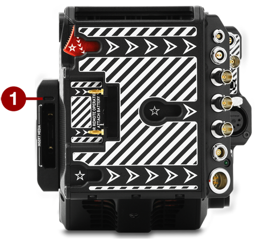
Figure: Media Bay LED
|
# |
LED |
Color/Flashing |
Description |
|---|---|---|---|
|
1 |
Media Status LED (Back of media bay) |
Off |
No media mounted |
|
Green |
Preview; media mounted; > 10% of media space available |
||
|
Amber |
Record finalizing or playback mode |
||
|
Amber flashing (slow) |
Formatting media |
||
|
Red flashing (slow) |
Media mounted; > 5% and ≤ 10% of media available |
||
|
Red flashing (fast) |
Media mounted; ≤ 5% of media available |
||
|
Red |
Recording; media mounted; > 10% of media available |
REC LED
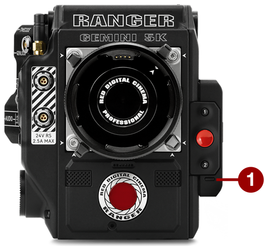
Figure: REC LED
|
# |
LED |
Color/Flashing |
Description |
|---|---|---|---|
|
1 |
Record Status LED1 |
Off |
Not recording, or media not mounted |
|
Red |
Recording |
- For more information on how to enable/disable this LED, go to Indicator. If media is not mounted, this LED is off.