Camera Body
This section describes the Front, Top, Left, Right, Back, and Bottom of the camera, and identifies the controls, buttons, Camera Body LEDs, and the lens mount on the body.
Camera Body Controls and Features
This section describes the controls and features of the camera.
Front

Figure: Camera Body Front Controls and Features
|
# |
Item |
Description |
|---|---|---|
|
1 |
Lens release |
Press to release RF-type lenses |
|
2 |
Mic 1 |
Left Internal Microphone channel |
|
3 |
Tally light |
Tally light (refer to Camera Body LEDs and Indicators) |
|
4 |
Mic 2 |
Right Internal Microphone channel |
|
5 |
Front REC button |
Press and release the REC button to toggle between record start and stop |
|
6 |
Lens locking ring |
Rotate to lock and unlock lenses |
Top

Figure: Camera Body Top Controls and Features
|
# |
Item |
Description |
|---|---|---|
|
1 |
LCD Touchscreen |
Camera Onboard LCD Touchscreen |
|
2 |
MENU (BACK) Button |
Menu button, Back button |
|
3 |
Up Arrow (LOCK) Button |
Navigates up in the menu and locks/unlocks the UI when pressed along with the other Lock button |
|
4 |
Down Arrow (LOCK) Button |
Navigates down in the menu and locks/unlocks the UI when pressed along with the other Lock button |
|
5 |
Select/Function Button |
Top Buttons Select Mode: Selects the highlighted Menu page item Top Buttons Function Mode: Alows you to access and adjust SDI Overlay settings |
|
6 |
Playback Button |
Opens the Playback page |
|
7 |
1/4-20 Mounting Holes |
1/4-20 mounting holes for optional accessories (refer to Outrigger Handle, DSMC3™ RED® Touch 7.0" LCD) |
|
8 |
Accessory Port |
Connection port for accessories (refer to Outrigger Handle, DSMC3™ RED® Touch 7.0" LCD) |
Left
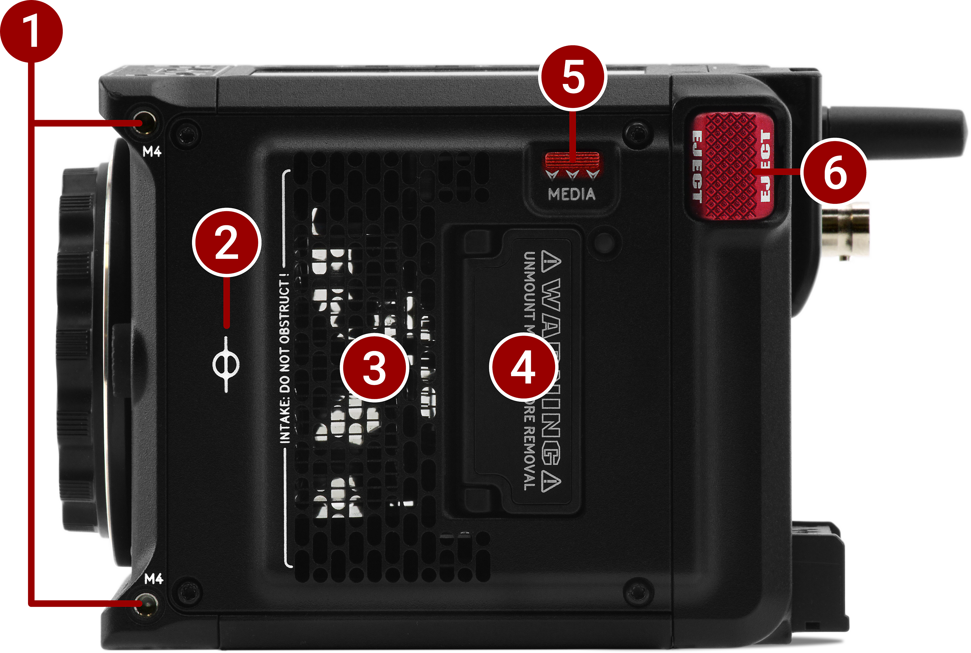
Figure: Camera Body Left Controls and Features
|
# |
Item |
Description |
|---|---|---|
|
1 |
M4 Mounting Holes |
Two (2) M4 mounting points for accessories |
|
2 |
Focus Plane |
Focus plane indicator symbol |
|
3 |
Air intake |
Air intake for thermal management |
|
4 |
Media compartment |
CFexpress Type B compartment |
|
5 |
Access media |
Latch for the CFexpress Type B media compartment door |
|
6 |
EJECT Button |
Micro-V battery eject button |
Right
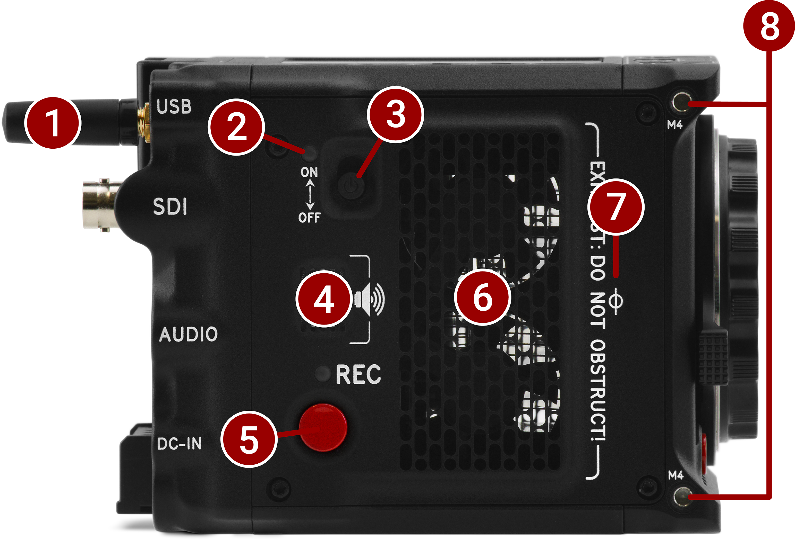
Figure: Camera Body Right Controls and Features
|
# |
Item |
Description |
|---|---|---|
|
1 |
Wireless antenna |
Wi-Fi antenna mounted to a female RP-SMA connector. Supports dual band 2.4 GHz or 5 GHz |
|
2 |
Power LED |
Displays the camera ready status (refer to Camera Body LEDs) |
|
3 |
ON/OFF switch |
Slide up to turn on the camera and slide down to turn off the camera |
|
4 |
Speaker |
Beep speaker for audible feedback |
|
5 |
Right REC button |
Assignable full-press and half-press button |
|
6 |
Exhaust |
Exhaust for thermal control |
|
7 |
Focus plane |
Focus plane indicator symbol |
|
8 |
M4 mounting holes |
Two (2) M4 mounting points for accessories |
Back
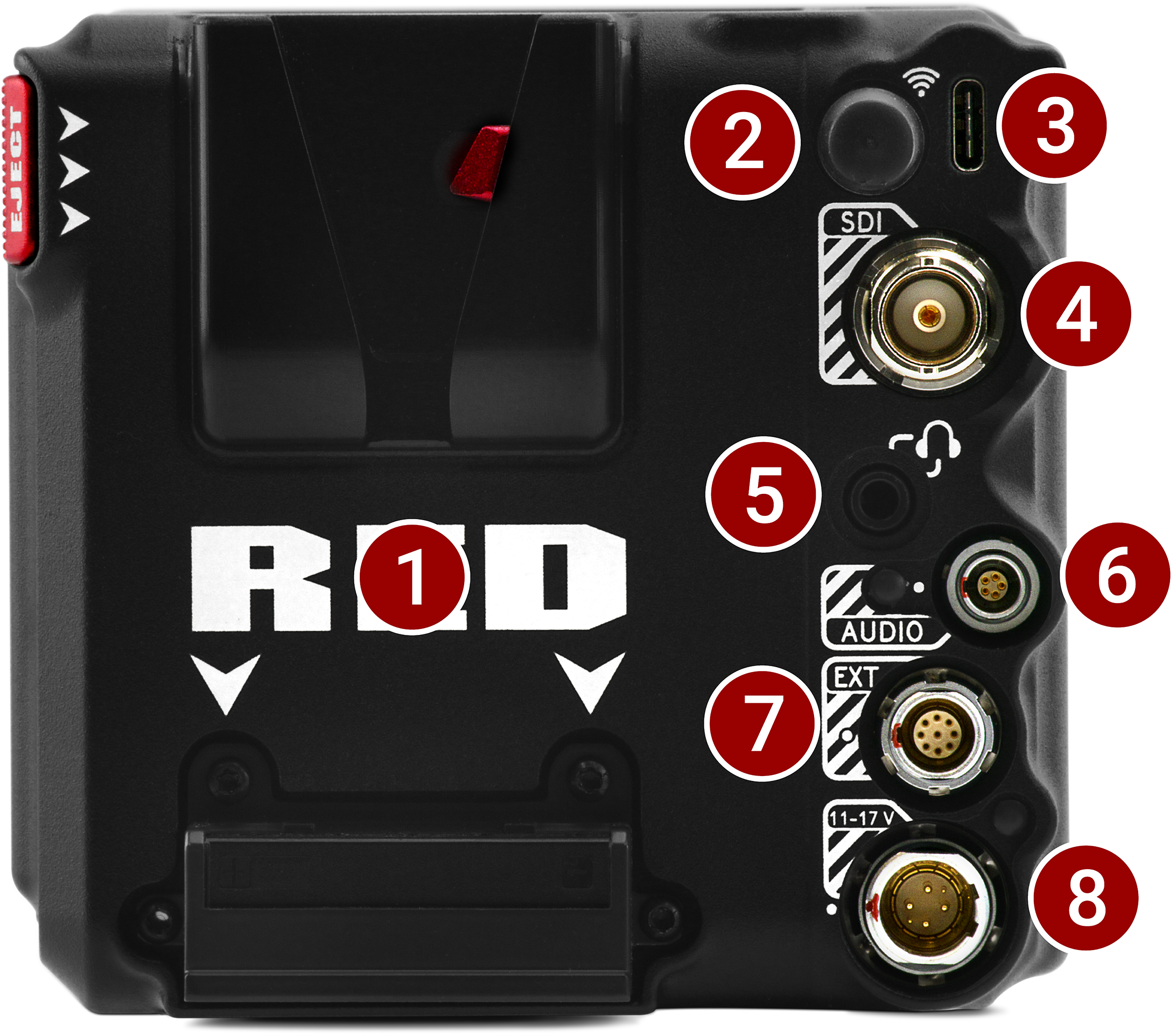
Figure: Camera Body Rear Controls and Features
|
# |
Item |
Description |
|---|---|---|
|
1 |
Micro V-Lock battery mount |
14.4 V Micro V-Lock mount(refer to REDVOLT® MICRO-V Battery and REDVOLT® NANO-V Battery) |
|
2 |
Wireless antenna |
Wi-Fi antenna mounted to a female RP-SMA connector. Supports dual band 2.4 GHz or 5 GHz |
|
3 |
USB Type-C port |
USB Type-C Port for USB-C connection |
|
4 |
12G-SDI port |
Full-size 12G-SDI BNC port for SDI monitor connection1,2 |
|
5 |
Headphone port |
3.5 mm stereo headphone output |
|
6 |
Audio port and LED |
5-Pin 00B ODU for 2 channel audio (Line, Mic, and +48V) |
|
7 |
9-pin Extension Port |
9-pin 0B ODU port (refer to Extension Port) |
|
8 |
6-pin DC-IN port and LED |
6-pin 1B ODU for DC-IN (11-17 Volts) and power status LED (refer to 6-pin DC-IN) |
- Use certified 12G-SDI cables.
- WARNING: Always connect the accessories' DC power cable (or batteries) before connecting the BNC SDI cable. Always remove the BNC SDI cable before removing the accessories' DC power cable (or batteries). For more information, refer to Preventing Damage to SDI Outputs.
Bottom

Figure: Camera Body Bottom Controls and Features
|
# |
Item |
Description |
|---|---|---|
|
1 |
Mounting Points |
One (1) 1/4"-20 mounting hole and one (1) 3/8"-16 mounting hole |
|
2 |
Registration Points |
Indented alignment points |
|
3 |
Service Port |
For RED service only - DO NOT REMOVE |
Camera Body LEDs
Front LED

Figure: Camera LED, Front
|
# |
Item |
Color |
Description |
|---|---|---|---|
|
1 |
Tally Indicator LED |
Red |
When enabled, this LED is ON when the camera is recording. For information about enabling this LED, refer to Indicators. |
Left Side LED
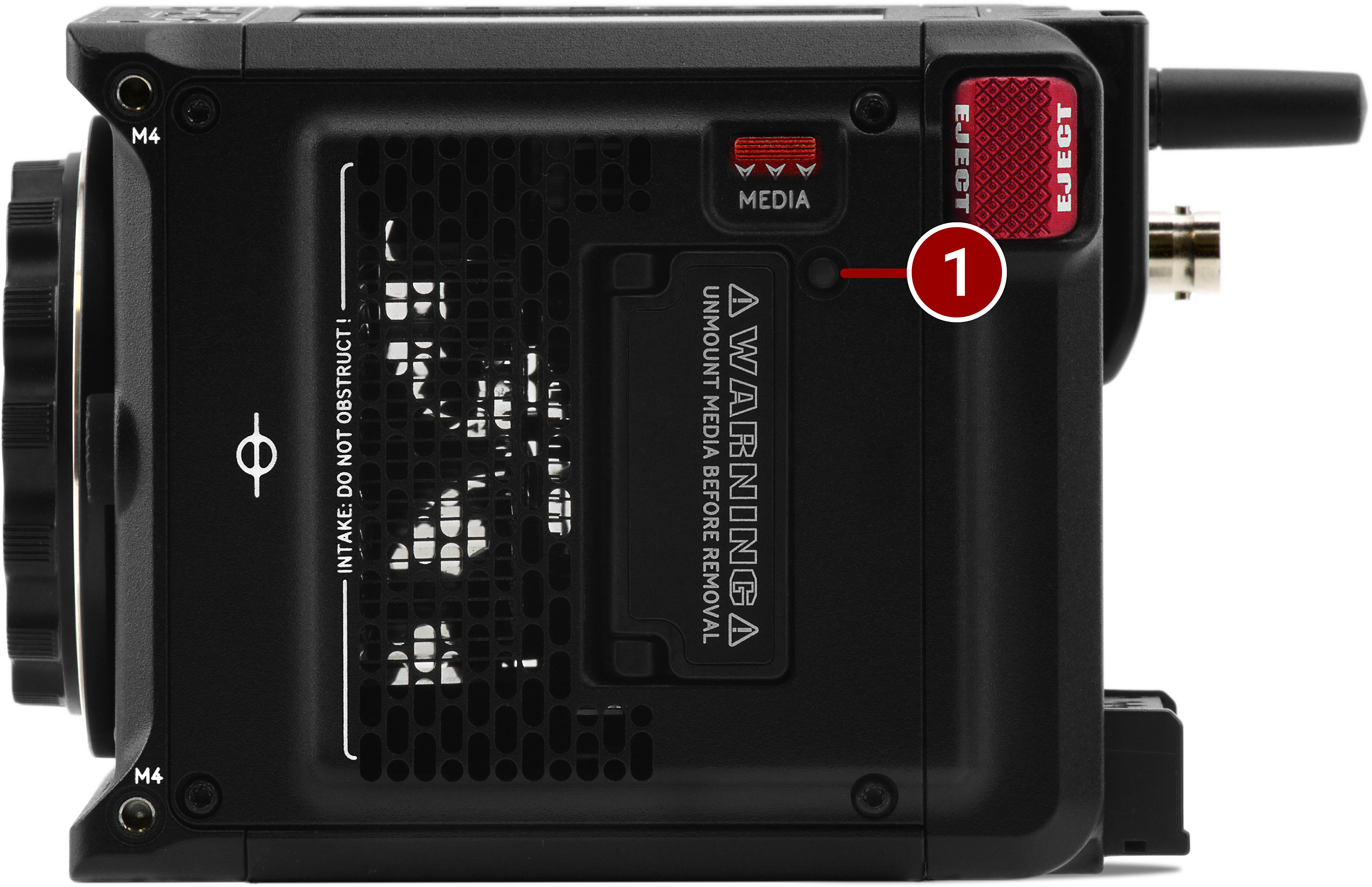
Figure: Camera LED, Left Side
|
# |
Item |
Color/Flashing |
Description |
|---|---|---|---|
|
1 |
CFexpress Media LED |
Off |
No media mounted |
|
Green |
Preview; media mounted with > 10% of media space available |
||
|
Amber |
Recording finalizing or playback mode |
||
|
Amber flashing slow |
Formatting media |
||
|
Red flashing slow |
Media mounted with >5% and <= 10% of media space available |
||
|
Red flashing fast |
Media mounted with <= 5% of media space available |
||
|
Red |
Recording |
Right Side LEDs
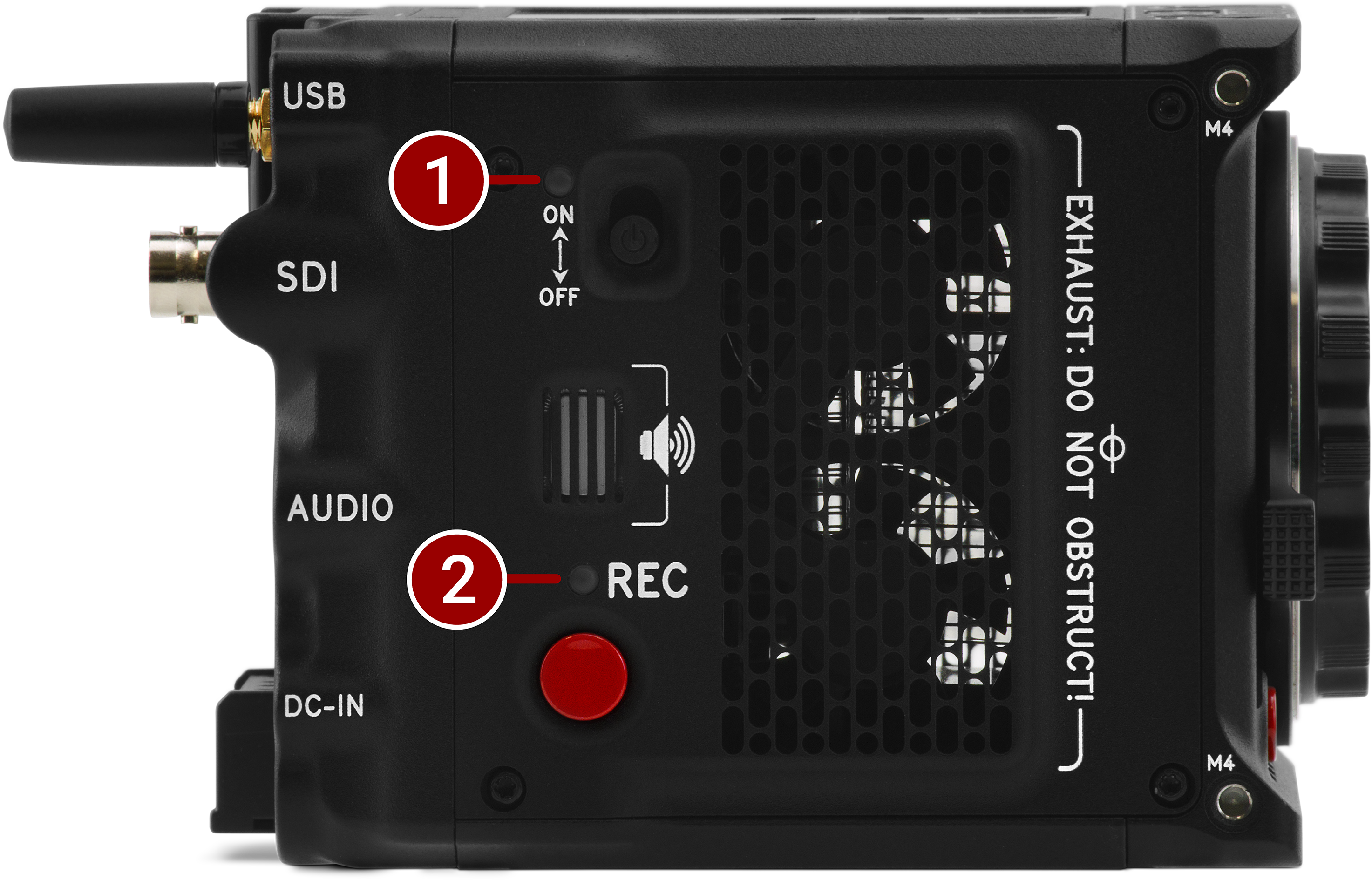
Figure: Camera LED, Right Side
|
# |
Item |
color/flashing |
Description |
|---|---|---|---|
|
1 |
Power Status (ON) |
Off |
Camera OFF |
|
Amber |
Camera booting |
||
|
Green |
Camera ON |
||
|
Amber flashing |
Camera on; 5 to 10 min of battery time available |
||
|
Red flashing |
Camera on; < 5 min of battery time available |
||
|
Red |
Camera shutting down |
||
|
2 |
Record Status (REC) |
Off |
No media present |
|
Green |
Ready to record |
||
|
Red |
Recording |
||
|
Amber |
Finalizing |
||
|
Red flashing slow |
Media mounted with >5% and <= 10% of media space available |
||
|
Red flashing fast |
Media mounted with <= 5% of media space available |
||
|
3 |
Power (firmware update) |
Flashing green |
Firmware update in progress |
|
Flashing red |
Firmware update error (refer to Upgrading the Firmware) |
Back LEDs
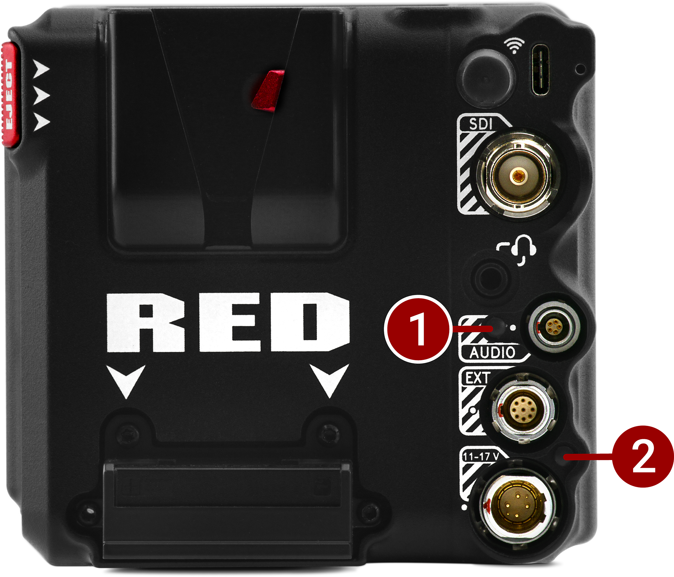
Figure: Camera LEDs, Rear
|
# |
Item |
Color |
Description |
|---|---|---|---|
|
1 |
Phantom power |
Blue |
Indicates that the +48 V Phantom Power is enabled |
|
2 |
DC-IN |
Green |
DC-IN is present and / or the battery is fully charged |
|
Flashing Amber |
Communicating with, and evaluating the battery |
||
|
Amber |
Charging connected batteries |
||
|
Red |
Error charging the batteries |